Hospitex Diagnostics EOS Bravo and EOS Bravo Plus Service Manual
31
8) measure the stabilizing tensions on the connectors J2 and J12 on the power board following the
below scheme:
- J12 pin 35, 36, 37, 38, 39, 40 = ground
- J12 pin 33, 34 = - 5 Vcc (acc. of 4,9 to 5,1)
- J12 pin 31, 32 = + 5 Vcc (acc. of 4,9 to 5,1)
- J12 pin 25, 26, 27, 28, 29, 30 = + 5,1 Vcc (acc. of 5,0 to 5,2)
- J2 pin 4, 5, 6, 8 = ground
- J2 pin 7 = + 6Vcc (variable of 5,2 to 6,5)
- J2 pin 1, 2, 3 = + 12, 5 Vcc (acc. of 12,4 to 12,6)
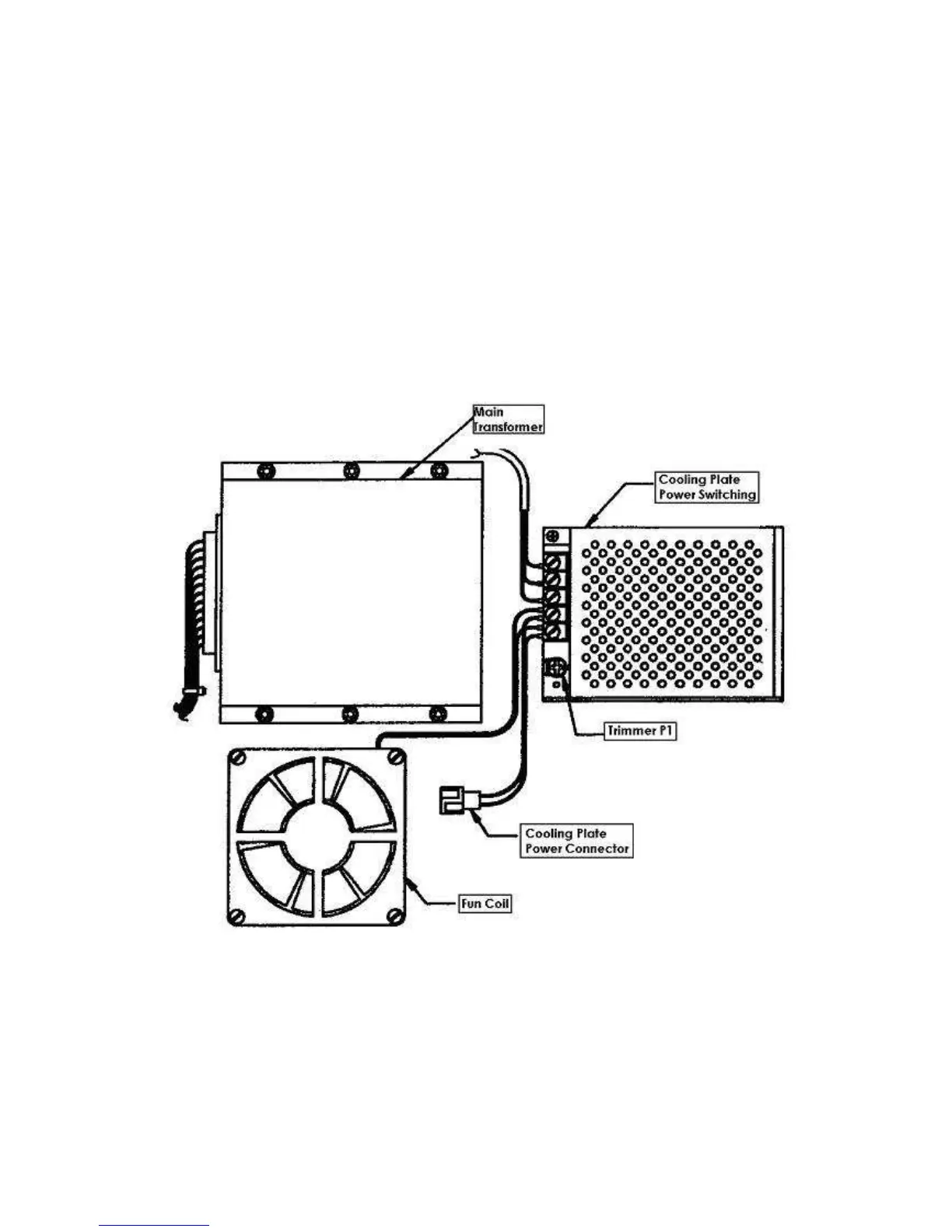
9) for the reagent cooling plate verify that the supplementary fan, situated beside the transformer,
is moving regularly without noise and that the air is directed towards outside of the instruments.
Connect the positive end of the tester on the pin 1 and the negative end on the pin 2 of the
alimentation connector of the reagent cooling plate and regulate the trimmer P1 of the
supplementary alimentator to obtain a tension between +14,01 and +14,02 Vcc.
10) leave the instrument on for some minutes, and then re-control again the tensions as per point 7
and 8 and verify that there are no problems due to the non correct assembly of the boards.
 Loading...