Hospitex Diagnostics EOS Bravo and EOS Bravo Plus Service Manual
32
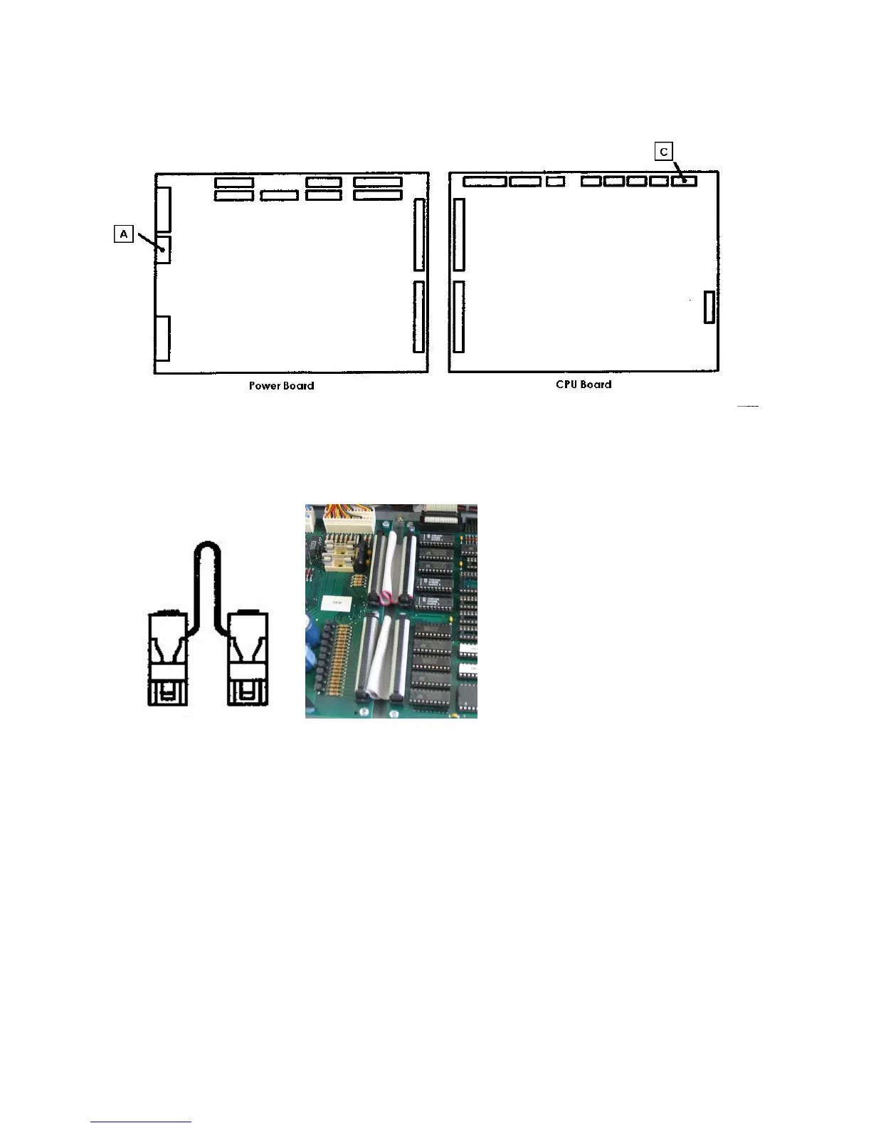
11) turn off the instrument and insert the connectors of the cablings on the Power and CPU board
as follows:
A = MX396 8 poles with the notes VID, V1, V2, L1 on the connector J2 of the power board
C = MX254 8 poles with the notes ST1, ST2 on the connector J10 of the CPU board
12) take the two board interconnection cables and insert them as a bridge between the
connectors J4 (CPU) <> J12 (power) and J5 (CPU) <> J11 (power).