Hospitex Diagnostics EOS Bravo and EOS Bravo Plus Service Manual
33
13) turn on the instrument
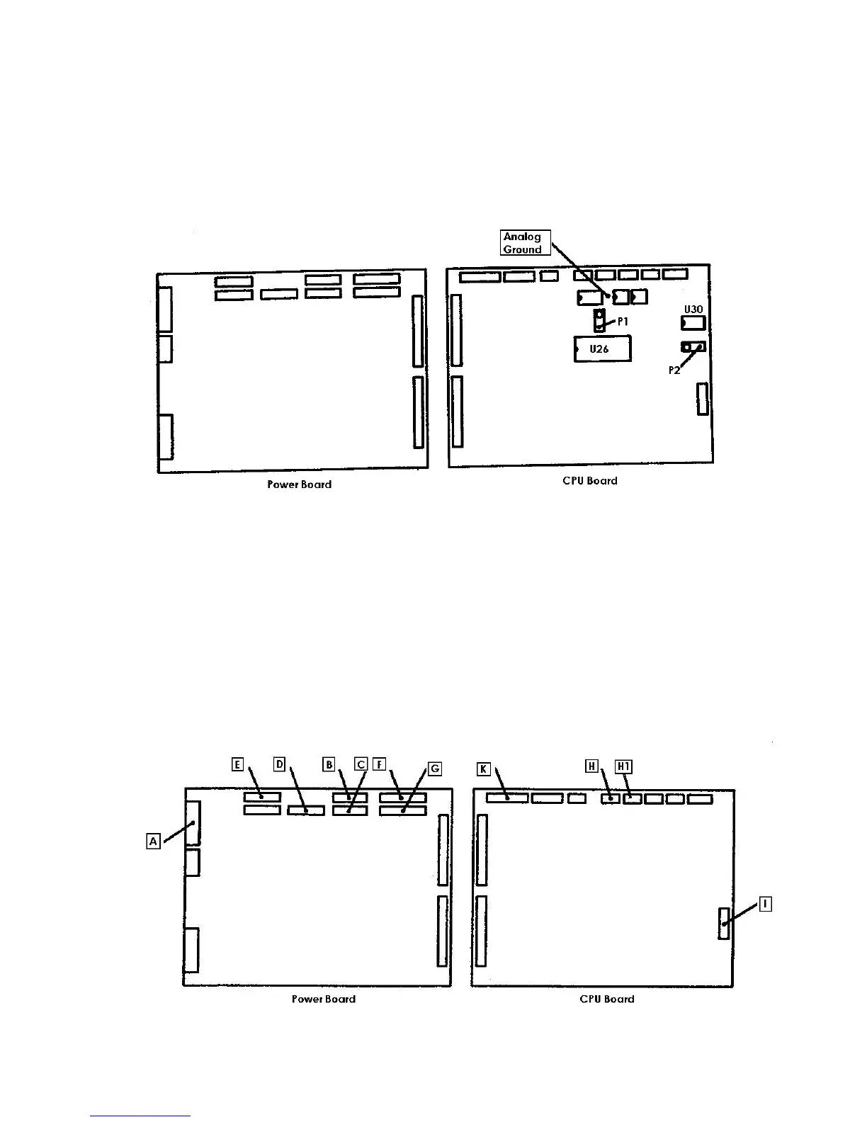
14) Check the two reference tensions VREF1 e VREF2 on the CPU board as follows:
- VREF1: connect the negative end of the tester on the analogical ground and the positive
end on the pin 2 of the U26 and then regulate the trimmer P1 to obtain a value of tension
equal to +1,000 Vcc ± 0,005V.
-
VREF2: connect the negative end of the tester on the analogical ground and the positive
end on the pin 6 of the U30 and then regulate the trimmer P2 to obtain a value of tension
equal to +2,731 Vcc ± 0,005V.
15) turn off the instrument and insert the connectors of the cabling on the boards as follows:
A = MX396 10 poles with the notes PT1, R1, R2, EV1 on the connector J3 of the power board
B = MX254 12 poles with the notes MIP, MOP, on the connector J4 of the power board
C = MX254 12 poles with the notes MFS, MPM on the connector J5 of the power board
D = MX254 12 poles with the notes MDS, MRP on the connector J6 on the power board
E = MX254 12 poles with the notes MSN, MAN on the connector J7 of the power board
F =MX254 15 poles with the notes SIP, SOP, SFS, SDS on the connector J9 on the power board
G = MX254 15 poles with the notes SRP, SSN, SAN on the connector J10 on the power board
H = MX254 6 poles with the note FD1 on the connector J6 of the CPU board
H1 = MX254 6 poles with the note FD2 on the connector J7 of the CPU board
I = Flat 16 poles on the serial port of the connector J1 of the CPU board
J = Not used
K =Flat 20 poles of the internal PC on the connector J3 of the CPU board
 Loading...