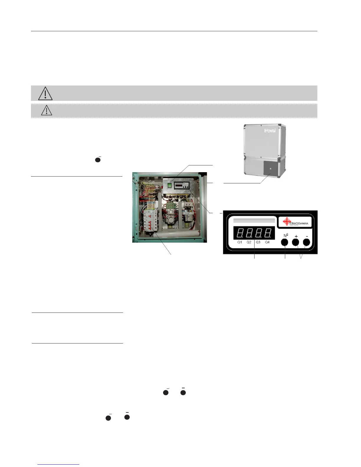
Internal Electric Panel(e)
Control Switch (g)
The control switch (g) must always be on and should only be turned of for service.
Pos. „1“ The control module (f) is on.
Pos. „0“ Control and monitoring of the heat pump is off.
Caution! The heat pump is not currentless!
In order to turn off power to the heat pump the fuses (h) must be shut off. (turn red lever to the left).
System Master Switch
In order to turn off power to the entire system, the customer must have an external master switch installed!
Operating Displays
Control Module type RAM100A
LED Display Field (3)
The basic display shows the current outside temperature.
The following operating parameters can be shown, one after another,
in the display field using the
N
o
button (1):
Para- Display
meters Designation Example
1 Outside Temperature 6.1
2 Evaporator Temperature 0.1
5 Current Difference
∆T 5.5
6 Reference Difference* 5.1
7 Current Operating Status
(various displays screens possible)
HP off 0
HP on 10
Difference Monitoring* 20
Defrosting Delay 21
Defrosting Process 22
Defrosting Shutdown Period 23
Defrosting Idle Period 25
8 Relay Status Q
1
-Q
4
Q
1
**
* Difference between Outside and Intake Gas Temperature
** Bars in display field over marking (e.g. Q
1
) = Relay on.
The basic display is shown again after the last parameter. After a one minute interruption, it switches back to the basic display.
Fault displays
If a fault occurs, it is shown in the LED display field (3):
Display
(blinking) Fault Cause/Mal function
AL1 Return too low
AL2 Low Pressure (N23)
AL3 High Pressure (N24)
AL4 Line Safety Switch (Q3),
Compressor/Ventilator
Er 1(P1) Outside Sensor defective
Er 2 (P2) Evaporator Sensor defective
In case a fault is displayed with an additional point (e.g. AL2. or Er1.), then other faults occurred additionally.
Reset Device (Confirmation)
In case the fault (AL2-AL4) is repaired,
the fault has to be acknowledged manually by pressing the
N
o
and in combination. In case of a defect temperature sensor
(Er1-Er2), the fault will be deleted automatically after replacing the sensor.
Caution!
By pressing the key combination
N
o
and for 3 seconds, all faults saved are acknowledged and deleted!
f
e
g
h
3 1 2
Plant Control - Internal Electric Panel
 Loading...