7.3 DISMANTLING PROCEDURE FOR ANNUAL INSPECTION (Continued)
Fig. 2
Fig. 3
NOTE: The indicator spindle has to clear a dowel pin which moves along the spiral groove in the
spindle, therefore this cover must be kept in an axial position when withdrawing until the spindle
clears the dowel pin (Fig 3). The LPI Sensor is housed inside a sensor well attached to the cover
and this must also be removed axially.
IMPORTANT: It is essential that the spiral groove engaging the dowel pin is marked for correct re-
assembly to avoid damage to the potentiometer.
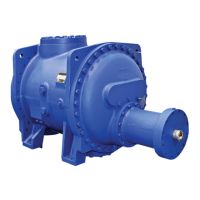
Move the slide valve to bring the actuator piston to the outer end of the cylinder. Do not move the
slide valve past its minimum position at the capacity stop as it may come off the guide block at the
inlet end of the compressor when unlocking the piston lockwasher and locknut.
Fig. 4 Fig. 5
Unlock the piston lockwasher and locknut and remove (Fig. 4).
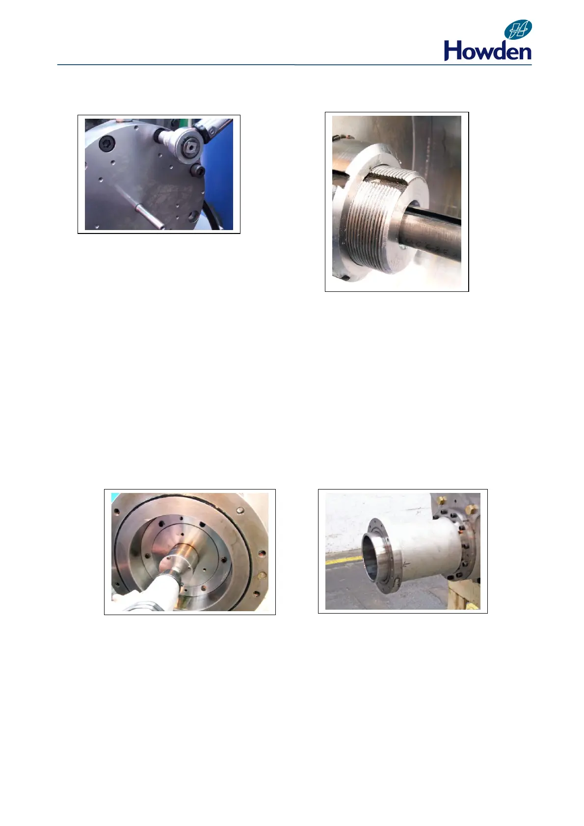
Remove the actuator stop sleeve, if fitted, from the cylinder bore (Fig. 5).
Withdraw the piston (Fig. 6) using the appropriate tool listed for the compressor size. See Section
9.3.