of
the
base plate with
the
flat
end of the
slide
bar
held flush
at the
forward
face
of the
base plate
and the
rearward offset portion
of the
slide
bar
rotated upward. Tighten
set
screws lightly. Next, Install
the
cable glide block
on
the
cables
by
putting
one
coble
In
each slot. Moke sure that
the
large
hole In
the
coble glide Is facing
the
correct direction, that is when
the
cable
glide
Is
Installed
on the
coble bar,
the
cables should
be
between
the
coble
bar and
the
string. Slip cable guard block over the rear end
of
the coble
bar
by pulling cables back. Loosen
the set
screws
In the
base plate
and
rotate
the slide
rod
until there
is
just enough offset
for
vanes
to
clear
the
cables.
Retlghten
the set
screws firmly.
For coble guard Installation opposite stabilizer bushing. Install
the
adjust-
able cable
bar In the
fixture provided with
the
rear offset portion rotated
away from string
and
lightly tighten
the
two
set
screws. Proceed In
the
some
manner
as
described above
and
tighten
the two set
screws firmly when
Installation
Is
complete.
You
now
hove Installed
a
Hoyt/Easton Coble Guard Control System which
unlike
any
other
con be
adjusted
for the
proper amount needed
for
vane
clearance. This system Improves accuracy
by
substantially reducing lateral
limb torque.
The
coble glide block reduces coble friction
and
wear. Next,
place
the
arrow rest
or
horizontal micro adjuster device (whichever type
supplied)
on the bow
Proceed with
the
following instructions
for
nocking
point placement.
INSTALLING THE NOCKING POINT
Install
the
enclosed clamp-on nocking point
on the
bowst/ing. Using
a bow
square, initially position
the
nocking point
on
th^ bowstring
so
that the nock
end
of the
arrow
is
approximately
%"
(1 crth) above square.
If
clamped
firmly
(but not too
tightly) over
a
monofilament center serving,
the
nocking
point
con be
threaded"
up and
down
the
serving while tuning your
bow
until
the
final adjustment
is
achieved, after which
it can be
ciamped tightly
in place.
•
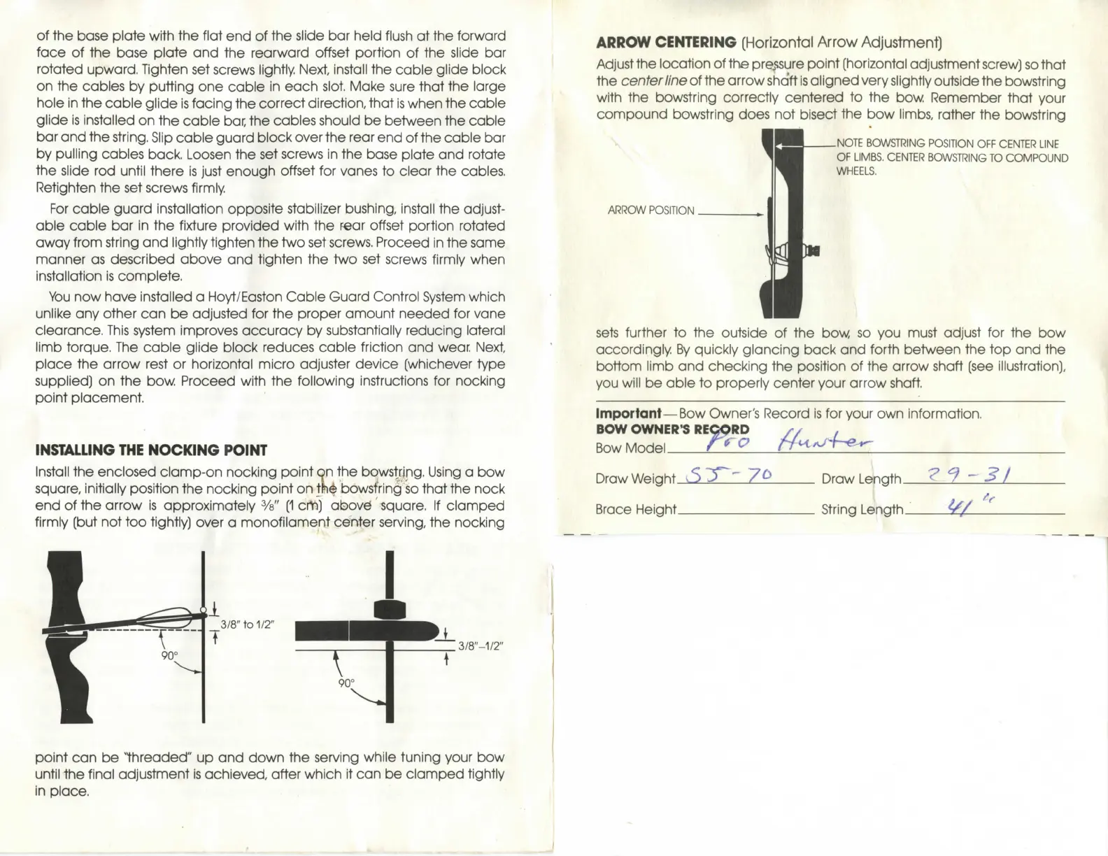
ARROW CENTERING
(Horizontal Arrow Adjustment)
Adjust the location
of
the pressure point (horizontal adjustment screw) so that
the center line
of
the arrow shaft is aligned very slightly outside the bowstring
with
the
bowstring correctly centered
to the bow.
Remember that your
compound bowstring does
not
bisect
the bow
limbs, rather
the
bowstring
\
ARROW POSITION
NOTE BOWSTRING POSITION OFF CENTER LINE
OF
LIMBS.
CENTER
BOWSTRING TO
COMPOUND
WHEELS.
sets further
to the
outside
of the bow so you
must adjust
for the bow
accordingly
By
quickly glancing back
and
forth between
the top and the
bottom limb
and
checking
the
position
of the
arrow shaft
(see
illustration),
you will
be
able
to
properly center your arrow shaft.
Important—Bow Owner's Record
Is for
your
own
Information.
BOW OWNER'S REQpRD
Bow Model-
Draw Weight.
_
Draw Length.
Brace Height String Length.
^/
 Loading...