GB
Contents
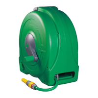
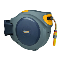
A
Autoreel
B
Wall Bracket
C
Feeder Hose
D
Threaded Tap Connector
E
Hose End Connector
F
Waterstop Connector
G
Wall Plugs and Screws
H
Hose Nozzle
Quick hints and tips
obstructs the reel from swinging freely through 180°.
mount the reel.
spirit level.
turning on water supply.
distance (15 to 30cm) away from the reel and then
walked back towards the reel.
Turn off the tap and let the water out of the hose by
opening the hose nozzle/gun.
Walk back to the reel with the end of the hose and
trigger the rewind mechanism by taking hold of the
hose near to the reel, and gently pull the hose about
15 to 30cm to release the latch.
(Ensure that nothing is obstructing the hose whilst
the rewind procedure is active.)
when not in use.
Assembly and installation
of the Auto Reel
TOOLS NEEDED:
SELECT A SUITABLE POSITION
FOR INSTALLATION
Fig 1.
suitable for use with indoor taps, unless used with
supplied)
Allow 65cm of clearance on both sides of the wall
bracket. (See Fig.1)
bracket should be mounted at least 1.60m from the
corner, and a hose guide should be used
MOUNT THE WALL BRACKET
Fig 2.
by releasing the locking clasp on the reel (Fig.2a).
The wall bracket can now be removed ready for
mounting.
•Important:Ensurethatthewallbracketisvertical
(withthepadlockloop(seefig6.a)pointingdown)
usingaspiritlevel,andthatthecorrectsizeholes
(7mmdiameterand50mmdeep)aredrilled
(Fig.2b).
(Contents G). The plugs and screws supplied are
designed for use on standard brick and concrete
should use screws and plugs appropriate for that
surface.
CONNECT THE FEEDER HOSE
AND FITTINGS
tap, replace it with a good quality 12.5mm (½”) hose.
Fig3–AttachingtheFeederHose:
and remove the side disc using a flat headed
screwdriver (Fig.3a).
put the nut over the hose (Fig.3c).
tighten the nut (Fig.3d). Ensure that the hose is
pushed all the way into the inlet. Re-fit the side disc
(Fig.3e).
Attach the hose end connector (Contents E) to the
free end of the feeder hose. Attach the water stop
connector (Contents F) to the watering hose and
connect the nozzle/gun supplied to the water stop
connector (Contents H) (Fig.3f).
 Loading...