EasyManuals Logo

HP 3312A Service Manual

HP 3312A
20 pages
To Next Page IconTo Next Page
To Previous Page IconTo Previous Page
Page #15 background imageLoading...
Page #15 background image
Model
3312A
Section
IV
SECTION
IV
THEORY
OF
OPERATION
41.
INTRODUCTION.
4-2.
This
section
contains
a
complete
theory
of
operation
for
the
Model
3312A
Function
Generator.
The
theory
is
divided
into
two
levels:
1.
Basic
Block
Diagram
Description
2.
Functional
Block
Diagram
Description
Detailed
circuit
descriptions
are
given
for
unique
complex
circuits.
These
descriptions
may
be
helpful
when
trouble-
shooting
the
instrument.
43.
DESCRIPTION.
4-4.
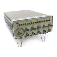
The
3312A
combines
two
separate,
independent
func-
tion
generators
referred
to
as
the
main
generator
and
the
modulation
generator.
The
main
generator
output
can
be
controlled
by
the
modulation
generator.
The
major
features
of
the
3312A
are
the
0.1
Hz
to
13
MHz
frequency
range
of
the
main
generator
and
the
AM,
FM,
sweep
and
tone
burst
capabilities
of
the
modulation
generator.
A
basic
block
diagram
of
the
3312A
is
shown
in
Figure
4-1,
4-5,
BASIC
BLOCK
DIAGRAM
DESCRIPTION.
4-6.
The
main.
generator
of
the
3312A
uses
a
voltage
to
frequency
conversion
technique.
A
triangle
waveform
is
generated
by
charging
and
discharging
a
capacitor
from
a
constant
current
source.
The
time
required
to
charge
and
discharge
the
capacitor
determines
the
period
of
one
cycle
and,
therefore,
the
frequency.
VOLTAGE
_
[COMPARATOR
ji
=
i
TUNING
|,
|
TRIANGLE
(^V
AMPLIFIER
GENERATOR
BURST
CONTROL
CONTROL
FM
AND
SWEEP
CONTROL
GENERATOR
3312
A
B
3954
|
SINE
av
SHAPER
a
MODULA
ON
OE
ele
ecaaadaniliad
4-7.
The
triangle
waveform
from
the
Triangle
Generator
is
applied
to
the
Voltage
Comparator
which
acts
as
an
amplitude
limiter.
As
the
triangle
waveform
alternately
crosses:
the
upper
and
lower
switching
levels
of
the
limiter
input,
a
square
wave
is
generated
at
the
output
of
the
Voltage
Comparator,
This
square
wave
is
fed
back
to
the
Triangle
Generator
where
it
controls
the
charge/discharge
cycle
of
the
triangle
output.
4-8.
To
obtain
a
sine
wave,
the
triangle
wave
is
shaped
by
a
diode
network
in
the
Sine
Shaper.
The
diode
network
serves
as
a
non-linear
load
which
varies
the
attenuation
of
the
input
triangle
according
to
its
level.
4.9.
The
modulation
generator
can
amplitude
modulate,
frequency
modulate,
sweep,
or
initiate
a
burst
from,
the
main
generator
output.
Sweep
and
frequency
modulation
modes
control
the
voltage
output
of
the
tuning
amplifier
which
determines
the
frequency.
In
amplitude
modulation,
the
main
signal
is
routed
through
a
balanced
modulator
where
it is
mixed
with
the
modulating
signal.
The
percent
of
modulation
is
controlled
by
the
level
of
the
modulating
signal.
4-10.
The
tone
burst
is
accomplished
by
gating
the
main
generator
output
on
and
off.
Multiple
or
single
cycle
operation
is
determined
by
the
duration
of
the
low
state
of
the
Burst
Control.
4-11.
The
output
amplifier
has
separate
parallel
paths
for
the
high
and
low
frequencies.
This
gives
it
wide
bandwidth
and
a
high
slew
rate
to
maintain
good
square
and
triangle
wave
shape
without
compromising
de
stability
and
low
offset.
An
integrated-circuit
operational
amplifier
is
used
Bickel
AS
ahhh,
A
OC
OFFSET
i
OUTPUT
A
P
pat-
AMPLIFIER
ATTENUATOR
g
[10
|:
100
H:
1000
|
AMPLITUDE
MODULATOR
Figure
4-1.
Basic
Block
Diagram.
4-]

Questions and Answers:

Question and Answer IconNeed help?

Do you have a question about the HP 3312A and is the answer not in the manual?

HP 3312A Specifications

General IconGeneral
BrandHP
Model3312A
CategoryInverter
LanguageEnglish

Related product manuals