IfiH
MANUAL
CHANGES
-hp-
MODEL 239A
DISTORTION MEASUREMENT SET
Manual Part
Number
00339-90001
|
New or
Revised Item
ERRATA.
Page 4-11,
Figure
4-12.
Change
the
part number
of the
SHIELD
(item 7)
from
1251-1073
to
1251-0173.
Page 4-11, Paragraph
4-25a.
The
INPUT
RANGE should be 0.1V,
not IV.
Page 4-12, Paragraph
4-26b.
The sentence
should read, "Connect
the equipment
as shown in Figure
4-
1 3 without the
1
00 kfl series
resistor."
Resistor
R67 and
R68 have replaced L3 and L4
for the prevention
pf
high
frequency
oscillation.
CHANGE
NO.
2
(applies to
instruments with serial numbers
1730A00409 and greater).
Page
6-5,
Table
6-3.
Change
A2R22 from
2100-0568 Resistor
Trimmer
100
11
10%
to
2100-3212 Resistor Trimmer 200 11
10%.
Page
6-6, Table
6-3.
Add
the
following part:
A2R43
0757-0400
Resistor 90.9
11 1
%
.1
25
W TC
=
0
+
-
1
00
|
8-11/8-12, Figure
8-12.
Chapei
no
01 mfd.
tile value
of capacitor Cl from
CHANGE
NO. 1 (applies
to instruments
with
ferial
numbers
1730A00266 and greater).
Page 6-9, Table
6-3.
Delete parts A4L3
and
A4L4 hp^
part
number
9170-0894.
Page
6-10, Table
6-3.
Add
the following
parts:
A4R67 0757-0407
Resistor
200 11 1
%
. 1
25
W
A4R68 0757-0407
Resistor 200
11 1% .1
25
W
Page
8-17.
Figure
8-15.
Delete
parts L3 and
L4
from
the schematic.
February
20,
1
983
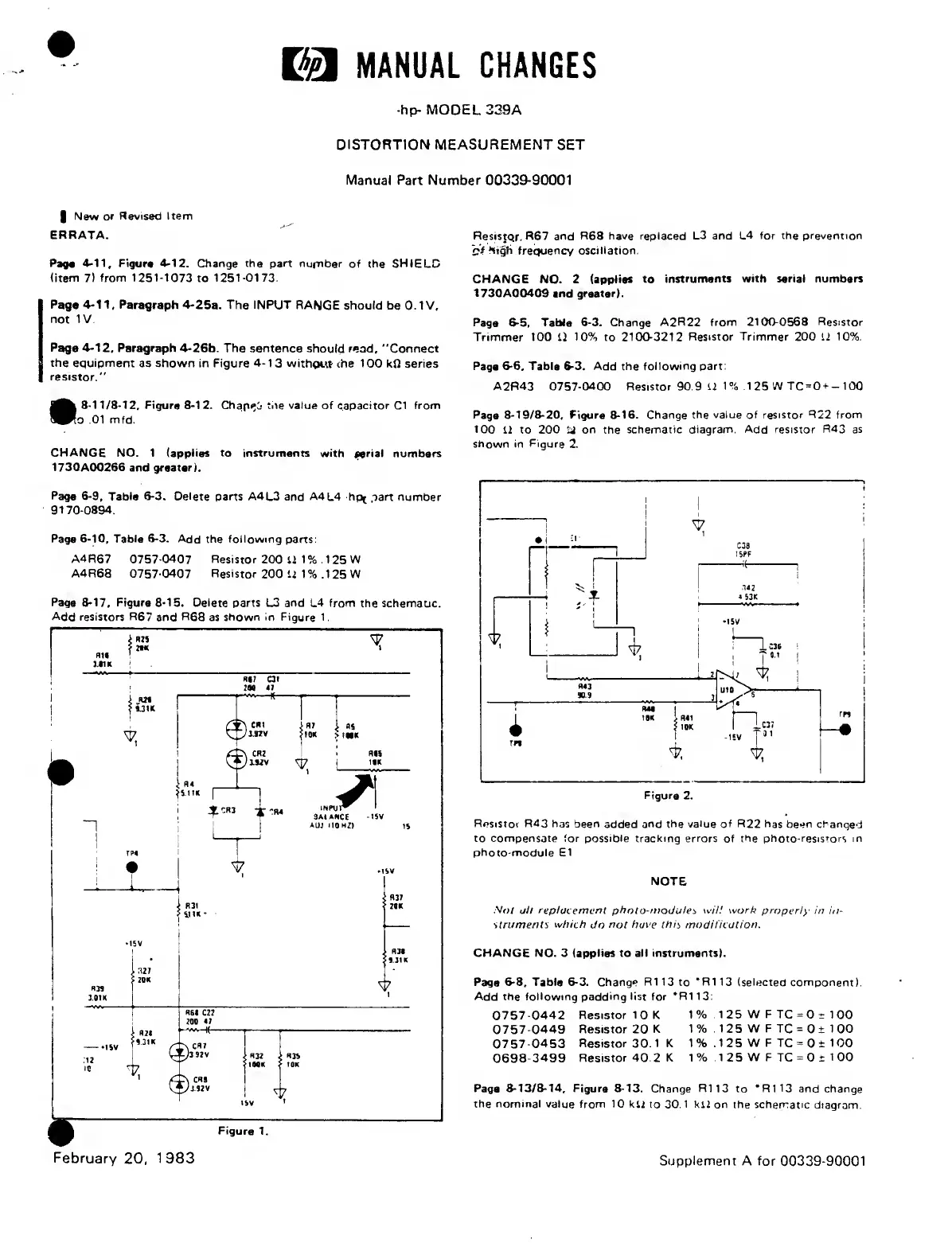
Page
8-19/8-20,
Figure
8-16.
Change the
value
of
resistor R22 from
100
11 to
200 ij on
the
schematic diagram.
Add
resistor
R43
as
shown
in Figure
2.
Figure
2.
Resistoi
R43 has
been
added
and the
value
of
R22
has
been changed
to compensate for possible tracking errors
of
the
photo-resistors
in
photo-module
El
NOTE
.Vo/ all replacement photo-modules wilt work
property in in-
struments
which
Jo
not have
this
modification.
CHANGE NO.
3
(applies to all instruments).
Page
6-8. Table
6-3.
Change
R1
13 to
*R1
13 (selected component).
Add the following padding list for
* R 1 13:
0757-0442
0757-0449
0757-0453
0698-3499
Resistor 1
0
K
Resistor 20
K
Resistor 30. 1 K
Resistor 40.2 K
1% 1
25
W F TC
=0
i 100
1% .125 W F
TC
=
0±
100
1% .125 W F TC
=
0
±
100
1
%
1
2 5
W F TC
=
0 ±
1 00
Page
8-13/8-14,
Figure
8-13.
Change
R113
to
*R113
and change
the
nominal
value from
10
kll
to
30.1
kll on the schematic
diagram.
Supplement A for 00339-90001
 Loading...


