2
of 8 MANUAL
CHANGES
Model
339A
This change
has
been
made
to
permit
compensation
for dif-
ferences
in the dynamic
characteristics
of FET’s used
for Q100.
The value
of *
R
1
13
is
selected to
minimize distortion
introduced
by
the
input amplifier stage.
CHARGE
HO.
4
(applies ts
alt
instmaeats).
Page
8-10.
Table
8-3.
Change
A4R23
from
0698-3445 Resistor
348
Q
1% to
0698-4450 Resistor
324 Q
1%. Change
A4R55
from
0698-4453 Resistor 402 Q
1
%
to
0698-3445 Resistor
348 H
1 %.
Page 8-17,
Figure
8-15.
Change
the value
of
R23
from 348 11
to
324
U and the value of
R55
from 402 11 ro 348 11 on the schematic
diagram.
These changes
have been
made to insure that
the proper
current is
available
to
drive photo-modules A3E1
and
A3E2.
CHANGE NO.
5
(applies to instruments with
serial numbers
1730A00451 and greater).
Page 6-7,
Table
6-3. Change
capacitor A3C302
from
A-
2628 (.03
mfd.) to
01
50-0052
(.05
mfd).
Page fi-8. Table
8-3.
Add
the
following resistor:
A3R314
0683-1035
Resistor 1
0
kfl 5% W4
W
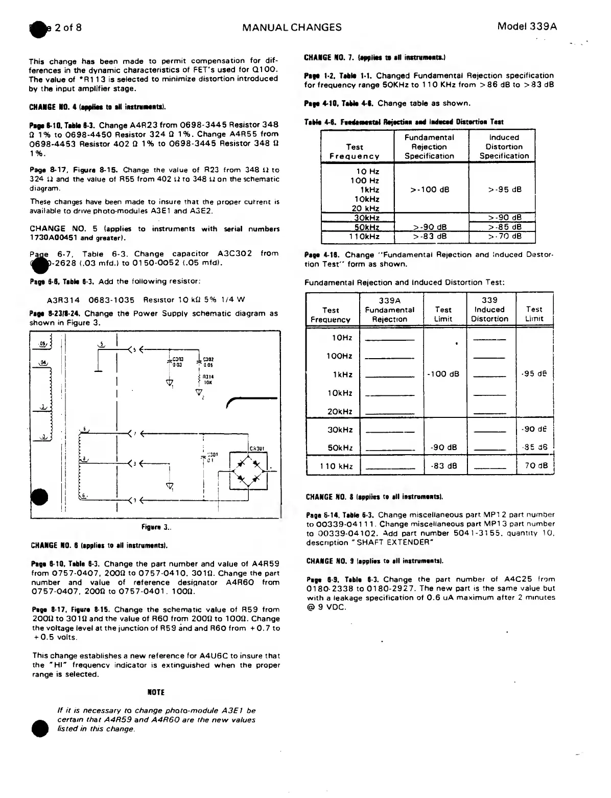
Page
8-2318-24. Change
the
Power Supply schematic
diagram
as
shown
in
Figure 3.
Figure
3.
CHANGE
NO.
8
(applies to all
instruments).
Page 8-10. Table 8-3. Change the part number and value of A4R59
from 0757-0407,
20011
to 0757-0410,
30111. Change
the part
number and value
of
reference designator A4R60
from
0757-0407,
2000 to
0757-0401.
1000.
Page 8-17,
Figure 8-15.
Change the schematic value
of
R59
from
20011 to 3010 and
the
value of R60 from
2000
to 1000. Change
the voltage
level at
the
junction of R59 and and R60
from +
0. 7 to
+ 0.5 volts.
This
change establishes
a
new reference for
A4U6C to
insure that
the
"HI"
frequency indicator is extinguished
when
the proper
range is
selected.
NOTE
CHARGE NO. 7.
(applies
to
all instruments.)
Pago
1-2, Table
1-1.
Changed
Fundamental Rejection specification
for frequency
range 50KHz to
1
1 0
KHz from >
86 dB to
> 83 dB
Page
4-10, Table
4-8.
Change
table
as
shown.
Tibia
4-8.
Fundamental Rejectien
aad Indecad Distortion Tnst
Fundamental Induced
Test
Rejection
Distortion
Frequency
Specification
Specification
10
Hz
100 Hz
1kHz
10kHz
20
kHz
>-100
dB
>-95
dB
30kHz
>-90
dB
50kHz
>-90
dB
>-85
dB
1 10kHz
>
-83
dB
>-70
dB
Psgn 4-18.
Change
"Fundamental Reaction
and Induced
Destor-
tion Test" form as
shown.
Fundamental Rejection and
Induced Distortion Test:
Test
Frequency
339A
Fundamental
Rejection
Test
Limit
339
Induced
Distortion
Test
Limit
10Hz
100Hz
1kHz
10kHz
20kHz
«
-100
dB
-95
dB
30kHz
50kHz
90
dB
Pgjggl
1
10
kHz
-83
dB
70 dB
CHANGE NO. 8
Isppiias
to sil
instruments).
Pays
6-14. Table
6-3.
Change
miscellaneous
part MP1
2
part number
to
00339-041 1
1
Change
miscellaneous part MP1
3
part
number
to
00339-04102. Add
part number
5041-31
55,
quantity
10.
description
"SHAFT
EXTENDER"
CHANGE NO. 8
(applies tn sil
instruments).
Page 8-9. Tnbln
6-3.
Change
the part
number of
A4C2 5
from
01 80 2338
to 01
80-2927.
The new part
is
the same
value
but
with
a leakage
specification
of
0.6 uA
maximum after
2
minutes
@
9
VDC.
If it
is necessary to change
photo-module A3E1
be
certain that
A4R59 and A4R60 are the new
values
listed in
this change.
 Loading...


