Model
339A
Section
VIII
indicates
the
rms value of the
input
signal
(voltmeter
function).
RELATIVE LEVEL
-
The relative
level
function
permits
the user to measure the rms
value
of the
input
signal relative to a pre-set
reference
(dB and
VU
measurements).
8-25.
In
addition to the Distortion ANalyzer
input,
the
339A also
includes an AM
DETECTOR
INPUT which
detects the
AM modulation
signal of an RF
carrier. This
allows
the
user to measure the total
harmonic
distortion
of
the modulation signal.
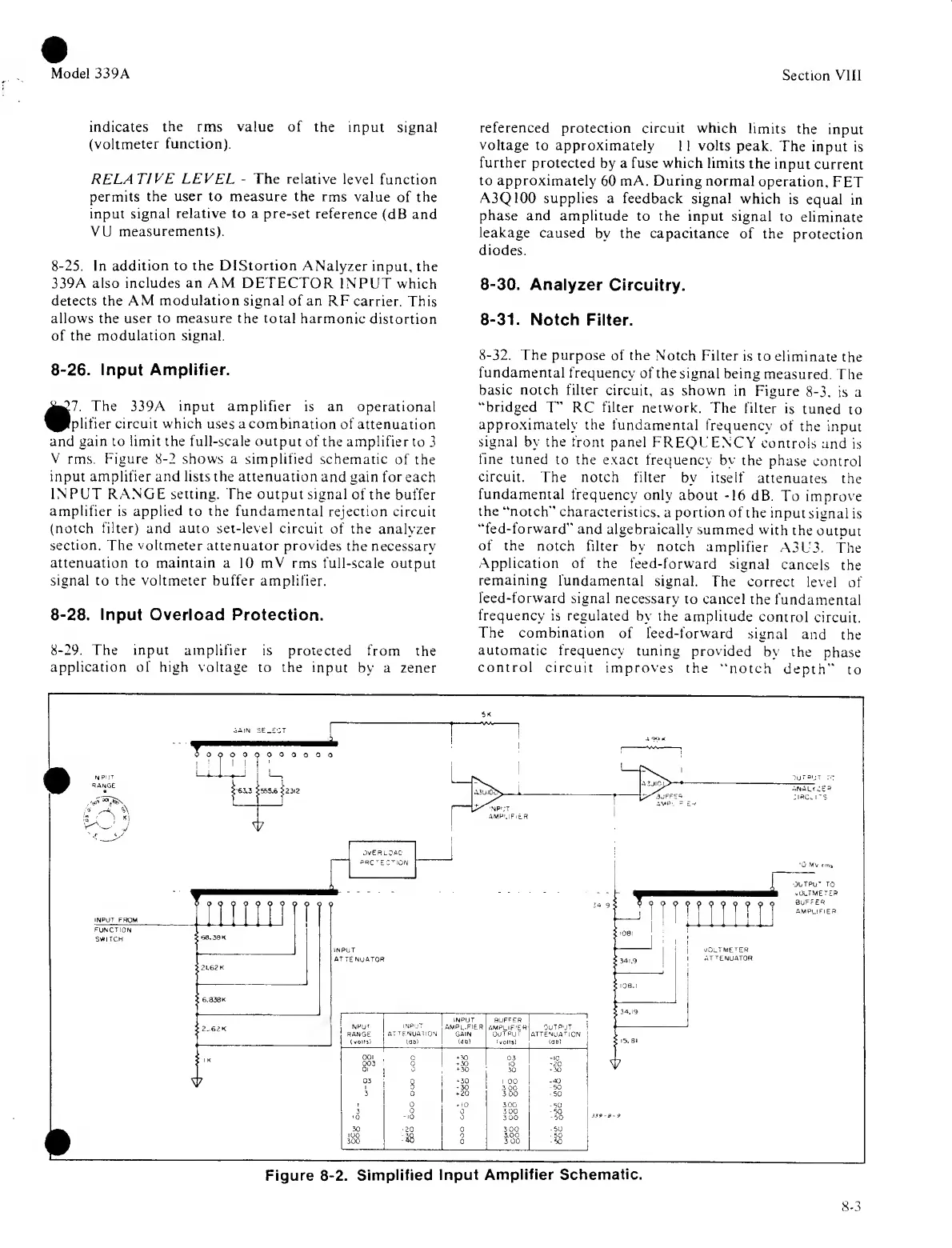
8-26.
Input Amplifier.
The 339A input amplifier
is an operational
^Plplifier
circuit which uses a combination
of
attenuation
and
gain to limit the full-scale output
of the
amplifier to
3
V rms. Figure
8-2
shows
a
simplified
schematic
of the
input amplifier and
lists
the attenuation
and gain
for
each
INPUT RANGE setting. The output
signal
of
the buffer
amplifier
is
applied
to
the fundamental
rejection circuit
(notch filter)
and
auto set-level
circuit
of the analyzer
section. The voltmeter attenuator
provides the necessary-
attenuation to maintain a
10
mV
rms
full-scale
output
signal to the voltmeter buffer
amplifier.
8-28.
Input Overload
Protection.
8-29.
The input amplifier
is protected
from the
application of high voltage
to the input
by a zener
referenced
protection circuit which
limits
the
input
voltage
to
approximately
1 1
volts
peak.
The
input is
further protected
by a fuse which limits
the
input
current
to approximately
60
mA. During normal
operation,
FET
A3Q100 supplies
a feedback signal
which
is
equal
in
phase
and amplitude
to the input signal
to
eliminate
leakage
caused
by the capacitance
of the
protection
diodes.
8-30.
Analyzer
Circuitry.
8-31.
Notch
Filter.
8-32.
The purpose
of the
Notch Filter is
to
eliminate
the
fundamental
frequency
of the signal
being
measured.
The
basic
notch filter
circuit, as shown
in Figure
8-3,
is a
"bridged
T” RC
filter
network.
The filter
is
tuned
to
approximately the
fundamental
frequency
of the
input
signal
by
the
front
panel
FREQUENCY
controls
and
is
fine tuned
to the exact
frequency by the
phase
control
circuit.
The
notch filter
by itself
attenuates
the
fundamental
frequency
only about
-16
dB.
To
improve
the
"notch"
characteristics,
a
portion
of
the input
signal
is
“fed-forward"
and algebraically
summed
with
the
output
of the
notch filter
by notch
amplifier
A3U3.
the
Application
of the
feed-forward
signal
cancels
the
remaining
fundamental signal.
The
correct
level
of
feed-forward
signal necessary
to cancel
the
fundamental
frequency
is regulated
by the amplitude
control
circuit.
The
combination
of feed-forward
signal
and
the
automatic
frequency
tuning provided
by the
phase
control circuit
improves
the
"notch
depth"
to
8-3
 Loading...


