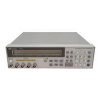
NOTE
If a power failure occurs, the 4278A will reset to the default settings. If you require
control settings other than the default settings, store them in a memory card and
load them into the 4278A as required. Make a backup copy for memory cards
containing important data. Keep one as a master and one for normal use.
3-9-3. MEMORY CARD ID COMMENTS
You can store an ID number on the memory card. When you press the 'STORE' softkey,
"COMMENT=" will be displayed on the Input Line. Enter an ID number using the numeric
keys, then press ENTER. The usable characters are zero to nine, the minus sign (-), and the
period (.). ID numbers up to ten characters can be stored in the memory card.
When the LOAD key is pressed with the card inserted, the ID number will be displayed on
the Message Line.
3-9-4. WRITE PROTECTION
The 4278A is equipped with a memory card write-protect switch, mounted internally. This
feature disables the 4278A's STORE function, and is useful it you want to retain specific
4278A control settings for everyday use, e.g., on a production line where it is not necessary
to store any information on a memory card, thereby making it impossible to accidentally
erase or overwrite memory card data. The procedure for setting the write protection switch
to ON is as follows.
1. Turn the 4278A off and remove the power cable. Allow a few minutes for the internal
capacitors to discharge.
WARNING'
DANGEROUS VOLTAGE MAY BE PRESENT IN THE 4278A EVEN THOUGH THE
POWER SWITCH IS OFF. BE SURE TO WAIT A FEW MINUTES FOR THE INTER-
NAL CAPACITORS TO DISCHARGE.
2. Remove the two feet at the back of the top cover.
3. Fully loosen the screw that secures the top cover.
4. Pull the top cover towards the rear of the 4278A and lift up to remove.
5. Loosen the five screws that secure the top shield plate (larger one).
6. Slide the top shield plate forward then lift it off.
7. Remove the A7 board. Figure 3-8 shows the A7 board's location.
3-15
 Loading...