3. HANDLER INTERFACE BOARD (OPTION 201)
If the +5V internal voltage (pin 16, 17 or 18 of the handler interface connector) is not
output, a fuse on the handler interface board (A32F1) has blown and must be replaced.
Two replacement fuses are furnished with the 4278A option 201. Additional fuses are
available from Hewlett-Packard. Order PN 2110-0046.
To replace A32F1, perform the following procedure.
1. To remove the handler interface board (A32), perform procedure 1 through 7 on
page 6-21.
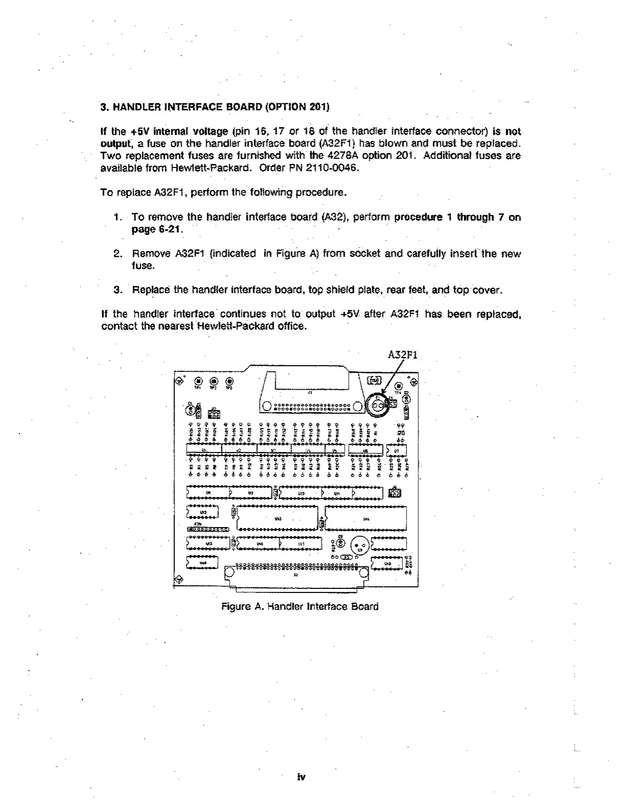
2. Remove A32F1 (indicated in Figure A) from socket and carefully insert the new
fuse.
3. Replace the handler interface board, top shield plate, rear feet, and top cover.
If the handler interface continues not to output +5V after A32F1 has been replaced,
contact the nearest Hewlett-Packard office.
A32F1
c? Q
511
0 inn,
9 99 t 9 9 9 9
Y ?
t-igg
• • •-•
O00e00000000000000000 0
•000eo000s0o0on0000s
:
9999 9 949 94 tt9 9 .99
S= tr. T.1 R' 98
666 i 6r:
• - A g gig f i z ; ; d tt
tx, vc y
.I
9' 9 9 9 9 4 9 9 49 t % t 9 9, T.
9 112
6 6 6 6 6 eb d d 6 6 6 d 6 6 6. 6
4 9 9 9 9 4 9 9
919* 91.92
6 6 6 6 6 d 6 6
1/6
-19.9ele-999
E. 4-"12
- 0 0 6 8 9 00 1"...""44..."*".*"...4 Et. — '.. •A e.
7
Ut4
OD CI I L90-0-9999-90647990496:091-0990-6-k- • 698 9 9A J6- Alb
••• t 6
• • 6 666666
U11
• •
"
(!)
LC-95—)r)
*,,U29 1
.^ : de
51:
Figure A. Handler Interface Board
iv