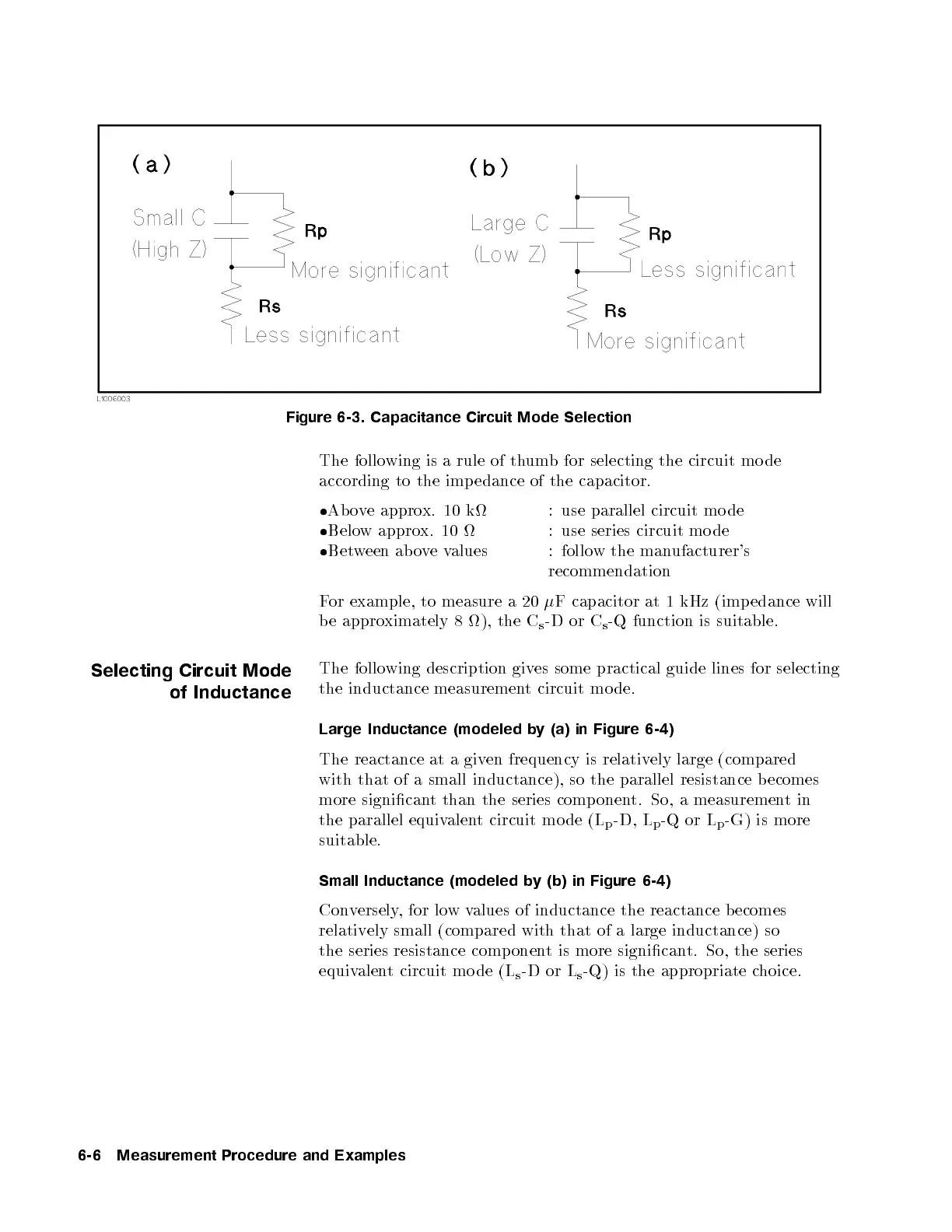
Figure 6-3. Capacitance Circuit Mode Selection
The following is a rule of thumb for selecting the circuit mo de
according to the imp edance of the capacitor.
Above approx. 10 k : use parallel circuit mo de
Below approx. 10 : use series circuit mo de
Between ab ovevalues : follow the manufacturer's
recommendation
For example, to measure a 20
F capacitor at 1 kHz (imp edance will
be approximately 8 ), the C
s
-D or C
s
-Q function is suitable.
Selecting Circuit Mode
of Inductance
The following description gives some practical guide lines for selecting
the inductance measurement circuit mo de.
Large Inductance (modeled by (a) in Figure 6-4)
The reactance at a given frequency is relatively large (compared
with that of a small inductance), so the parallel resistance becomes
more signicant than the series component. So, a measurementin
the parallel equivalent circuit mo de (L
p
-D, L
p
-Q or L
p
-G) is more
suitable.
Small Inductance (modeled by (b) in Figure 6-4)
Conversely, for lowvalues of inductance the reactance b ecomes
relatively small (compared with that of a large inductance) so
the series resistance comp onent is more signicant. So, the series
equivalent circuit mo de (L
s
-D or L
s
-Q) is the appropriate choice.
6-6 Measurement Procedure and Examples


 To Next Page