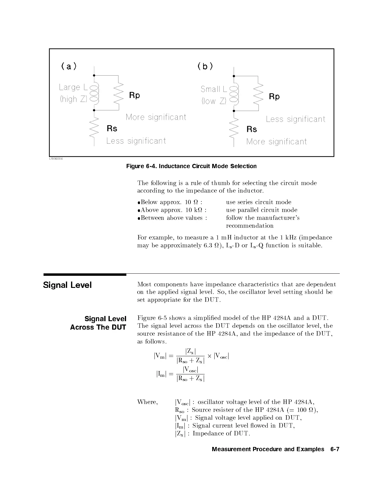
Figure 6-4. Inductance Circuit Mode Selection
The following is a rule of thumb for selecting the circuit mo de
according to the imp edance of the inductor.
Below approx. 10 : use series circuit mo de
Above approx. 10 k : use parallel circuit mo de
Between ab ovevalues : follow the manufacturer's
recommendation
For example, to measure a 1 mH inductor at the 1 kHz (imp edance
may b e approximately 6.3 ), L
s
-D or L
s
-Q function is suitable.
Signal Level
Most comp onents have imp edance characteristics that are dependent
on the applied signal level. So, the oscillator level setting should b e
set appropriate for the DUT.
Signal Level
Across The DUT
Figure 6-5 shows a simplied mo del of the HP 4284A and a DUT.
The signal level across the DUT depends on the oscillator level, the
source resistance of the HP 4284A, and the imp edance of the DUT,
as follows.
j
V
m
j
=
j
Z
x
j
j
R
so
+Z
x
j
2j
V
osc
j
j
I
m
j
=
j
V
osc
j
j
R
so
+Z
x
j
Where,
j
V
osc
j
: oscillator voltage level of the HP 4284A,
R
so
: Source resister of the HP 4284A (= 100 ),
j
V
m
j
: Signal voltage level applied on DUT,
j
I
m
j
: Signal current level owed in DUT,
j
Z
x
j
: Imp edance of DUT.
Measurement Procedure and Examples 6-7


 To Next Page