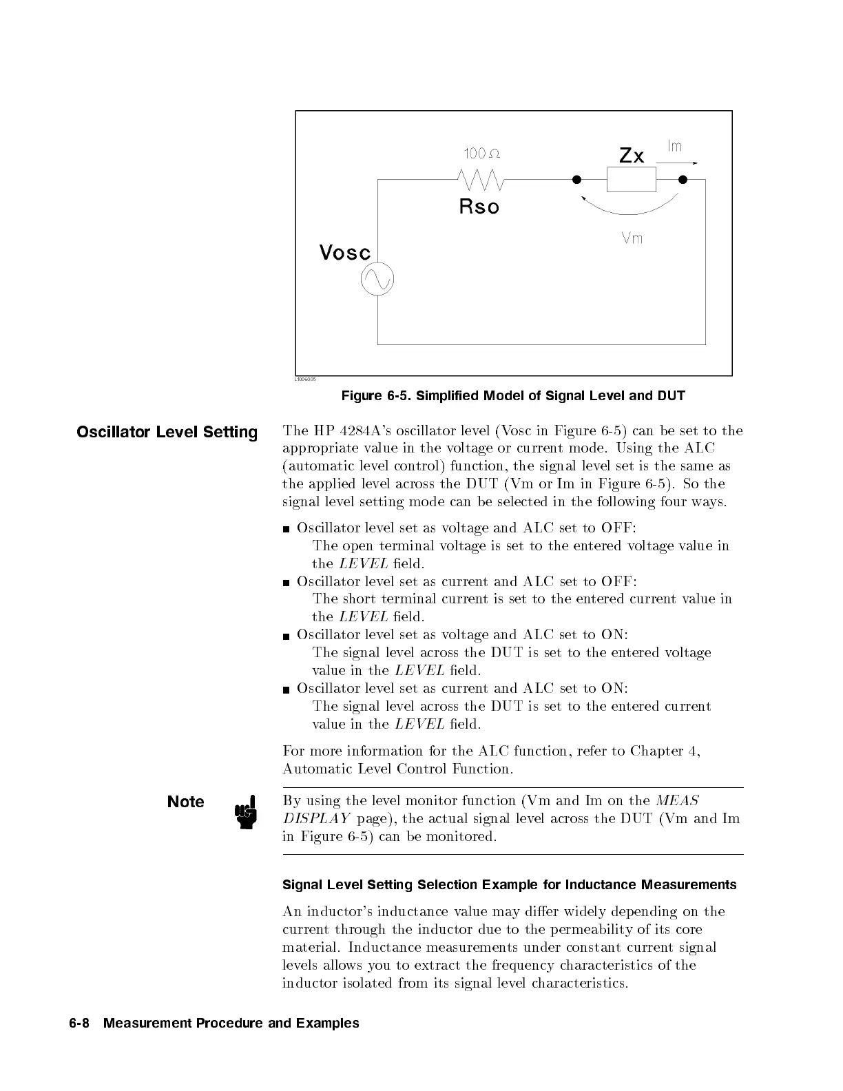
Figure 6-5. Simplified Model of Signal Level and DUT
Oscillator Level Setting
The HP 4284A's oscillator level (Vosc in Figure 6-5) can be set to the
appropriate value in the voltage or current mo de. Using the ALC
(automatic level control) function, the signal level set is the same as
the applied level across the DUT (Vm or Im in Figure 6-5). So the
signal level setting mo de can be selected in the follo
wing four ways.
Oscillator level set as voltage and ALC set to OFF:
The op en terminal voltage is set to the entered voltage value in
the
LEVEL
eld.
Oscillator level set as current and ALC set to OFF:
The short terminal current is set to the entered currentvalue in
the
LEVEL
eld.
Oscillator level set as voltage and ALC set to ON:
The signal level across the DUT is set to the en
tered voltage
value in the
LEVEL
eld.
Oscillator level set as current and ALC set to ON:
The signal level across the DUT is set to the entered current
value in the
LEVEL
eld.
For more information for the ALC function, refer to Chapter 4,
Automatic Level Control Function.
Note
By using the level monitor function (Vm and Im on the
MEAS
DISPLAY
page), the actual signal level across the DUT (Vm and Im
in Figure 6-5) can b e monitored.
Signal Level Setting Selection Example for Inductance Measurements
An inductor's inductance value may dier widely dep ending on the
current through the inductor due to the p ermeability of its core
material. Inductance measurements under constant current signal
levels allows you to extract the frequency characteristics of the
inductor isolated from its signal level characteristics.
6-8 Measurement Procedure and Examples


 To Next Page