To make constant current level measurements, set appropriate
oscillator level in currentvalue, and set ALC to ON. The signal
current level through the inductor will b e constant.
Four-Terminal Pair
Configuration
Generally,anymutual inductance, interference of the measurement
signals, and unwanted residual factors in the connection metho d
incidental to ordinary termination metho ds will have signicant
eects on the measurements, especially at a high frequency. The
HP 4284A employs the four-terminal pair measurement conguration
which p ermits easy, stable, and accurate measurements and avoids
the measurement limitations inherent to such factors.
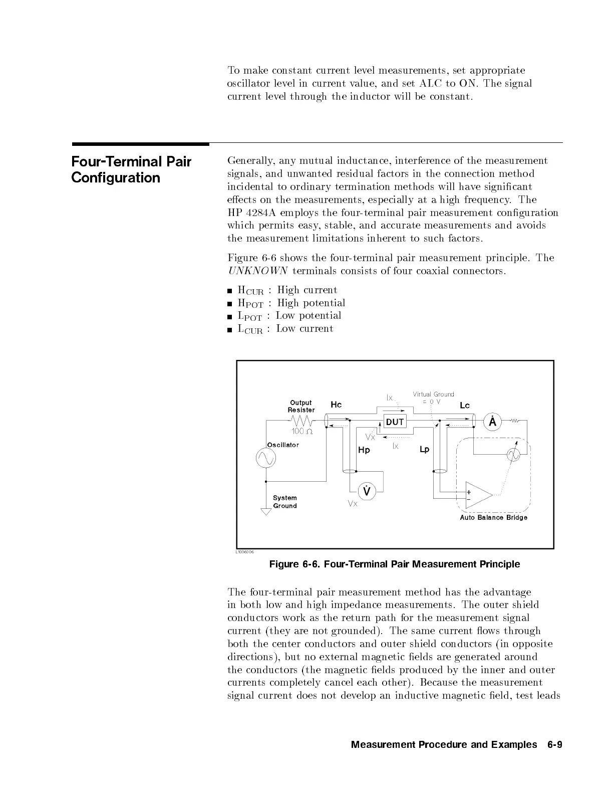
Figure 6-6 shows the four-terminal pair measurement principle. The
UNKNOWN
terminals consists of four coaxial connectors.
H
CUR
: High current
H
POT
: High potential
L
POT
:Low p otential
L
CUR
:Low current
Figure 6-6. Four-Terminal Pair Measurement Principle
The four-terminal pair measurement metho d has the advantage
in both low and high imp edance measurements. The outer shield
conductors work as the return path for the measurement signal
current (they are not grounded). The same currentows through
both the center conductors and outer shield conductors (in opposite
directions), but no external magnetic elds are generated around
the conductors (the magnetic elds pro duced b
y the inner and outer
currents completely cancel each other). Because the measurement
signal current do es not develop an inductive magnetic eld, test leads
Measurement Procedure and Examples 6-9


 To Next Page