If the device do es not have four-terminal pair measurement
terminals, measure the device using a direct coupling test xture
(such as the HP 16047A/C/D).
3. On the
CORRECTION
page, enter the measured values obtained
in step 2 as the
REF A
and
REF B
values with the function used
in step 2.
Parasitics Incident
to DUT Connection
You should consider that some parasitics remain in measurement
path even after performing corrections, as follows.
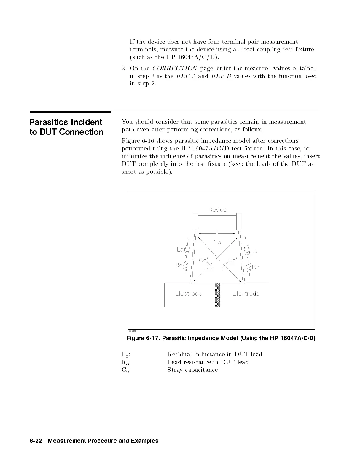
Figure 6-16 shows parasitic imp edance mo del after corrections
performed using the HP 16047A/C/D test xture. In this case, to
minimize the inuence of parasitics on measurement the values, insert
DUT completely into the test xture (keep the leads of the DUT as
short as p ossible).
Figure 6-17. Parasitic Impedance Model (Using the HP 16047A/C/D)
L
o
: Residual inductance in DUT lead
R
o
: Lead resistance in DUT lead
C
o
: Stray capacitance
6-22 Measurement Procedure and Examples


 To Next Page