Press
4
DISPLAYFORMAT
5
.
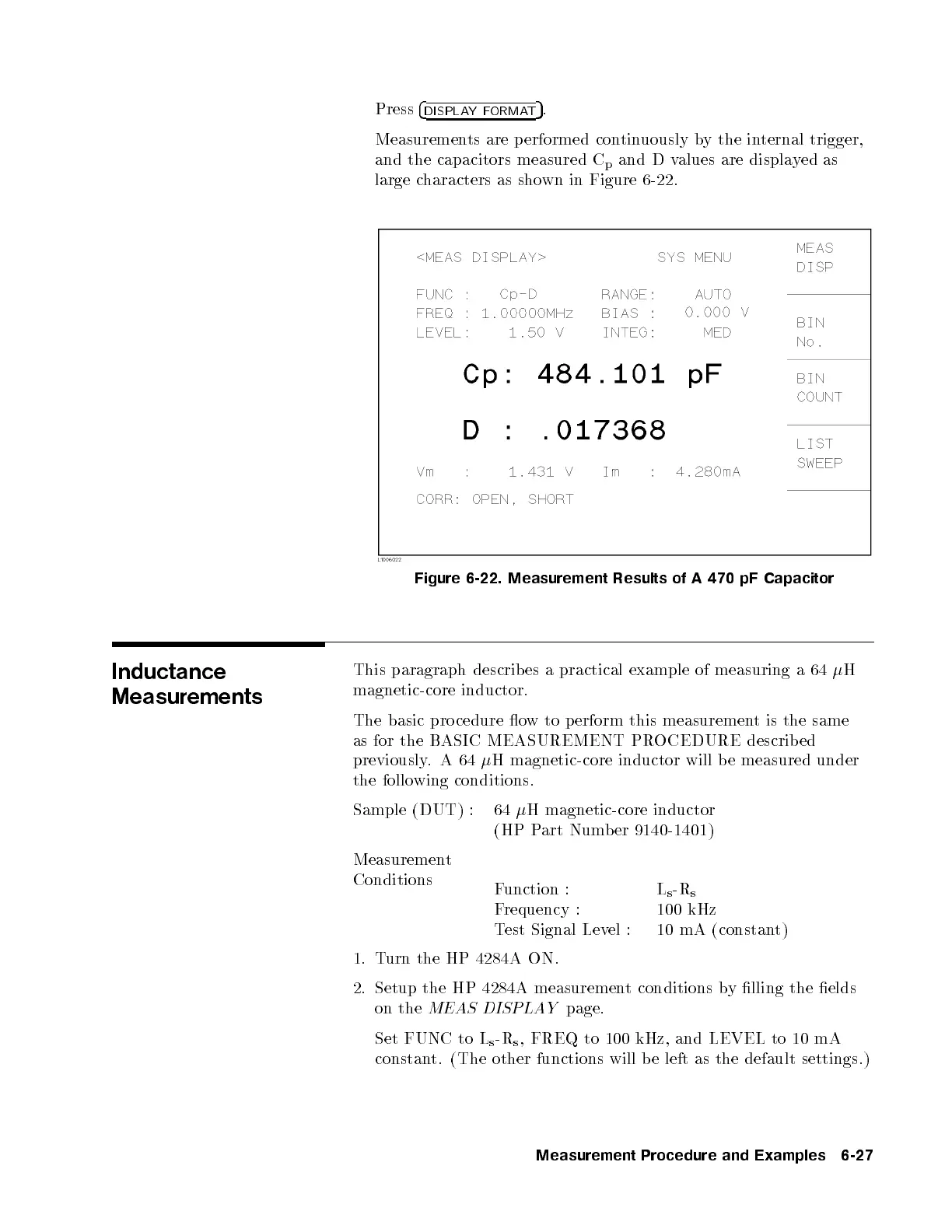
Measurements are performed continuously by the internal trigger,
and the capacitors measured C
p
and D values are displayed as
large characters as shown in Figure 6-22.
Figure 6-22. Measurement Results of A 470 pF Capacitor
Inductance
Measurements
This paragraph describ es a practical example of measuring a 64
H
magnetic-core inductor.
The basic pro cedure ow to perform this measurement is the same
as for the BASIC MEASUREMENT PROCEDURE describ ed
previously.A64
H magnetic-core inductor will b e measured under
the following conditions.
Sample (DUT) : 64
H magnetic-core inductor
(HP Part Numb er 9140-1401)
Measurement
Conditions
Function : L
s
-R
s
Frequency : 100 kHz
Test Signal Level : 10 mA (constant)
1. Turn the HP 4284A ON.
2. Setup the HP 4284A measurement conditions by lling the elds
on the
MEAS DISPLAY
page.
Set FUNC to L
s
-R
s
, FREQ to 100 kHz, and LEVEL to 10 mA
constant. (The other functions will b e left as the default settings.)
Measurement Procedure and Examples 6-27


 To Next Page