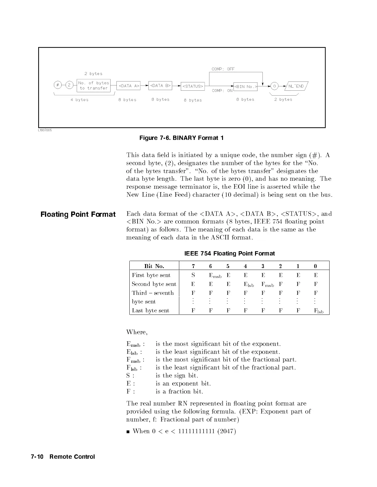
Figure 7-6. BINARY Format 1
This data eld is initiated by a unique co de, the number sign (#). A
second byte, (2), designates the numb er of the bytes for the \No.
of the bytes transfer". \No. of the bytes transfer" designates the
data byte length. The last byte is zero (0), and has no meaning. The
response message terminator is, the EOI line is asserted while the
New Line (Line Feed) character (10 decimal) is being sent on the bus.
Floating Point Format
Each data format of the
<
DATAA
>
,
<
DATAB
>
,
<
STATUS
>
, and
<
BIN No.
>
are common formats (8 bytes, IEEE 754 oating p oint
format) as follows. The meaning of each data is the same as the
meaning of each data in the ASCII format.
IEEE 754 Floating Point Format
Bit No. 7 6 5 4 3 2 1 0
First byte sent S E
msb
E E E E E E
Second byte sent E E E E
lsb
F
msb
F F F
Third { seventh F F F F F F F F
byte sent
.
.
.
.
.
.
.
.
.
.
.
.
.
.
.
.
.
.
.
.
.
.
.
.
Last byte sent F F F F F F F F
lsb
Where,
E
msb
: is the most signicant bit of the exponent.
E
lsb
: is the least signicant bit of the exponent.
F
msb
: is the most signicant bit of the fractional part.
F
lsb
: is the least signicant bit of the fractional part.
S: is the sign bit.
E: is an exponent bit.
F: is a fraction bit.
The real number RN represented in oating p oint format are
provided using the following formula. (EXP: Exponent part of
number, f: Fractional part of numb er)
When 0
<
e
<
11111111111 (2047)
7-10 Remote Control


 To Next Page