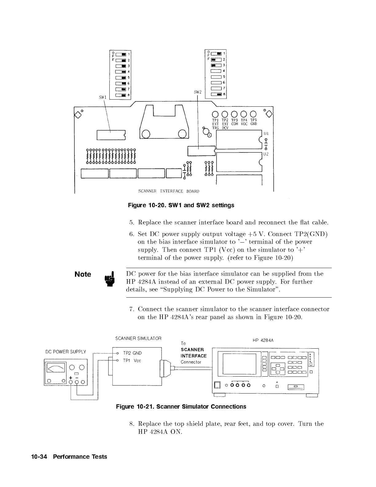
Figure 10-20. SW1 and SW2 settings
5. Replace the scanner interface board and reconnect the at cable.
6. Set DC p ower supply output voltage +5 V. Connect TP2(GND)
on the bias interface simulator to '
0
' terminal of the p ower
supply. Then connect TP1 (Vcc) on the simulator to '+'
terminal of the power supply. (refer to Figure 10-20)
Note
DC p ower for the bias interface simulator can be supplied from the
HP 4284A instead of an external DC p o
wer supply.For further
details, see \Supplying DC Power to the Simulator".
7. Connect the scanner simulator to the scanner interface connector
on the HP 4284A's rear panel as shown in Figure 10-20 .
Figure 10-21. Scanner Simulator Connections
8. Replace the top shield plate, rear feet, and top co
ver. Turn the
HP 4284A ON.
10-34 Performance Tests


 To Next Page