Supplying DC Power
to the Simulator
This paragraph shows the pro cedure supplying +5 V DC to the Bias
Interface Simulator or the Scanner Simulator from the HP 4284A
interior.
Procedure:
1. Disconnect the power cable from the HP 4284A and allow1
minutes for the internal capacitors to discharge.
Warning
Dangerous energy/voltage exists when the HP 4284A is in operation,
and for a time after it is powered down. Allow 1 minutes for the
internal capacitors to discharge.
2. Disconnect the two rear feet whichlock the top cover and rear
panel together.
3. Fully lo osen the top cover retaining screws lo cated on the rear of
the top cover.
4. Slide the top cover towards the rear and lift it o. The top shield
plate will b e visible.
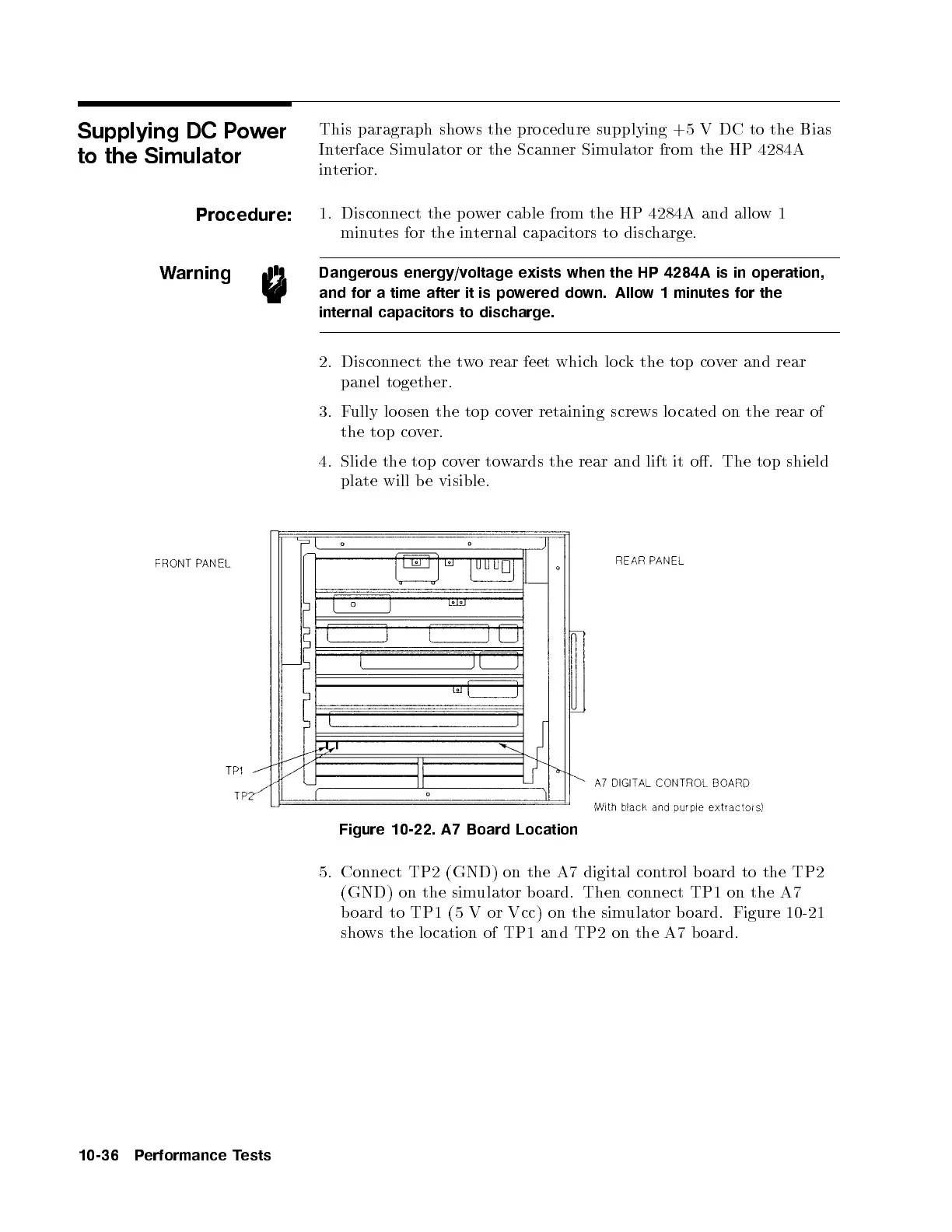
Figure 10-22. A7 Board Location
5. Connect TP2 (GND) on the A7 digital con
trol board to the TP2
(GND) on the simulator b oard. Then connect TP1 on the A7
board to TP1 (5 V or Vcc) on the simulator b oard. Figure 10-21
shows the lo cation of TP1 and TP2 on the A7 b oard.
10-36 Performance Tests


 To Next Page