•
Model 436A
General Information
SECTION
I
GENERAL
INFORMATION
1-1. INTRODUCTION
1-2. This manual provides information pertaining
to
the
installation, operation, testing, adjustment
and maintenance
of
the
HP
Model 436A Power
Meter.
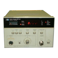
1-3. Figure 1-1 shows the Power Meter with
accessories supplied.
1-4. Packaged with this manual is an Operating
Information Supplement. This
is
simply a copy
of
the
first three sections
of
this manual. This
supplement should be
kept
with the instrument for
use by the operator. Additional copies of
the
Operating Information Supplement may be
ordered through
your
nearest Hewlett-Packard
office. The part numbers are listed
on
the title page
of
this manual.
1-5. On the title page
of
this manual, below
the
manual
part
number, is a "Microfiche"
part
number. This number may be used to order
4x6-inch microfilm transparencies
of
the manual.
The microfiche package also includes
the
latest
Manual Changes supplement
as
well
as
all
pertinent
Service Notes.
1-6. SPECIFICATIONS
1-7. Instrument specifications are listed in
Table 1-1. These specifications are
the
performance
standards or limits against which
the
instrument
may be tested.
1-8. INSTRUMENTS COVERED
BY
MANUAL
1-9. Power Meter Options 003, 004, and 022 are
documented in this manual. The differences are
noted
in the appropriate location such as
OPTIONS in Section I,
the
Replaceable Parts List,
and
the
schematic diagrams.
1-10. This instrument has a two-part serial
number. The first four digits and the letter
comprise the serial number prefix. The last five
digits form the sequential suffix
that
is unique
to
each instrument. The contents
of
this manual
apply directly
to
instruments having the same serial
number prefix(es) as listed under SERIAL
NUMBERS
on
the title page.
1-11. An instrument manufactured after
the
printing
of
this manual may have a serial prefix
that
is
not
listed on
the
title page. This unlisted
serial prefix indicates
that
the
instrument
is
different from those documented in this manual.
The manual for this instrument is supplied with a
yellow Manual Changes supplement
that
contains
change information
that
documents the
differences.
1-12. In addition
to
change information,
the
supplement
may
contain information
for
cor-
recting errors in the manual. To keep this manual
as current and accurate
as
possible, Hewlett-
Packard recommends
that
you
periodically request
the
latest Manual Changes supplement. The
supplement for this manual is keyed
to
the
manual's
print
date and
part
number,
both
of
which appear
on
the
title page. Complimentary
copies
of
the
supplement are available frorri
Hewlett-Packard.
1-13.
For
information concerning a serial
number
prefix
not
listed on
the
title page
or
in the Manual
Changes supplement,
contact
your
nearest Hewlett-
Packard office.
1-14. DESCRIPTION
1-15. The Power Meter is a preclSlon digital-
readout instrument capable
of
automatic
and
manual measurement
of
RF
and Microwave power
levels.
It
is designed for interconnection with a
compatible Power Sensor (refer
to
Table 1-1,
Specifications)
to
form a complete power measure-
ment
system. The frequency and power range
of
the
system are determined
by
the particular Power
Sensor selected for use. With
the
Power Sensors
available, the overall frequency range
of
the system
is
100
kHz
to
18
GHz,
and
the
overall power range
is
-70
to
+35 dBm.
1-16. Significant operating features
of
the
Power
Meter are as follows:
• Digital Display: The display is a four-digit,
seven-segment LED, plus a sign when in the
dBm
or
dB (REL) mode.
It
also has under- and
1-1

 Loading...