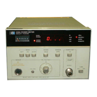
•
Model
436A
Operation
SECTION
Ill
OPERATION
3-1.
INTRODUCTION
~-2.
Thi~
section provides complete operating
information
for
the
Power Meter. Included in
the
section are a description
of
all front- and rear-panel
controls, connectors, and indicators (panel
features), operator's checks, operating instructions,
power measurement accuracy considerations, and
operator's maintenance.
3-3.
Since
the
power
meter
can be operated locally
as
well as remotely via
the
Hewlett-Packard
Inter-
face Bus (Option
022),
the
information in this
section
is
arranged accordingly. All information
unique
to
a particular operating configuration
is
designated
as
such; where
no
distinction
is
made,
the
information is applicable
to
both
standard and
optional instrument operation.
34.
PANEL
FEATURES
3-5.
Front
and rear panel features
of
the
Power
Meter are described in Figure 3-1. This figure
contains a detailed description of
the
controls,
connectors and indicators.
3-6.
OPERATOR'S
MAINTENANCE
3·7.
The only maintenance
the
operator
should
normally perform is replacement
of
the
primary
power fuse located within Line Module Assembly
All.
For
instructions on
how
to
change
the
fuse,
refer
to
Section
II,
Line Voltage Selection.
Make sure that
only
fuses with the required
rated current and
of
the specified
type
(normal blow, time delay, etc.)
are
used for replacement. The use
of
repaired
fuses and the short-circuiting
of
fuse-
holders
must
be
avoided.
3-8.
OPERATOR'S
CHECKS
3-9. A procedure
for
verifying
the
major functions
of
the
Power
Meter is provided in Figure 3-2. The
procedure is divided
into
two
parts: Local
Opera-
tion
and
Remote
Hewlett-Packard Interface Bus
Operation.
For
a standard instrument
it
is
only
necessary
to
perform
the
Local
Operation pro-
cedure.
For
units equipped with the remote
option,
the
Local Operation procedure should be
performed
first
to
establish a reference against
which
remote
operation can
be
verified.
Informa-
tion
covering remote programming
of
the
Power
Meter
is
provided in
the
following paragraphs, and
a Hewlett-Packard Interface Bus Verification
Pro-
gram is provided in
Section VIII, Service.
3-10. LOCAL OPERATING INSTRUCTIONS
3-11. Figure 3-3 provides general instructions for
operating
the
Power
Meter via
the
front-panel
controls.
I WARNING
I
Any
interruption
of
the protective
(grounding) conductor (inside or outside
the instrument) or disconnecting the
protective earth terminal
is
likely to make
this instrument dangerous. Intentional
interruption
is
prohibited.
3-1

 Loading...