•
•
•
Model 436A
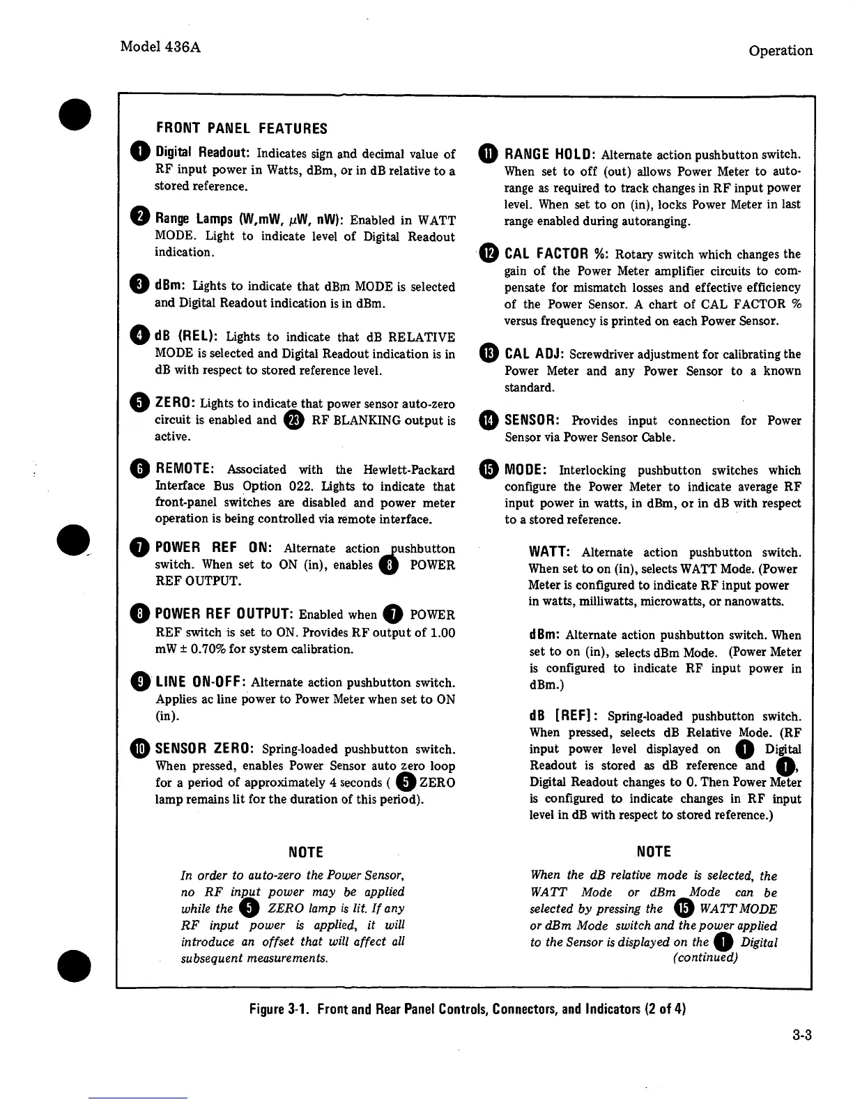
FRONT
PANEL
FEATURES
0
Digital
Readout:
Indicates sign and decimal value
of
RF input power in Watts, dBm, or in
dB
relative to a
stored reference.
0
Range
Lamps
(W,mW,
µW,
nW):
Enabled in WATT
MODE. Light to indicate level
of
Digital Readout
indication.
0
dBm:
Lights to indicate that
dBm
MODE
is
selected
and Digital Readout indication
is
in dBm.
0
dB
(REL):
Lights
to
indicate that
dB
RELATIVE
MODE
is
selected and Digital Readout indication
is
in
dB
with respect
to
stored reference level.
9
ZERO:
Lights
to
indicate that power sensor auto-zero
circuit
is
enabled and 9 RF BLANKING
output
is
active.
0
REMOTE:
Associated with the Hewlett-Packard
Interface
Bus
Option 022. Lights to indicate that
front-panel switches are disabled and power meter
operation is being controlled
via
remote interface.
8
POWER
REF
ON:
Alternate action
.fushbutton
switch.
When
set to
ON
(in), enables U
POWER
REF OUTPUT.
0
POWER
REF
OUTPUT:
Enabled when 8
POWER
REF switch
is
set to
ON.
Provides
RF
output
of
1.00
mW± 0.70% for system calibration.
0
LINE
ON-OFF:
Alternate action pushbutton switch.
Applies ac line power to Power Meter when set
to
ON
(in).
Ci)
SENSOR
ZERO:
Spring-loaded pushbutton switch.
When
pressed, enables Power Sensor auto zero loop
for a period
of
approximately 4 seconds ( 0 ZERO
lamp remains lit for the duration of this period).
NOTE
In order to auto-zero the Power Sensor,
no
RF
inp_ut
power
may
be
applied
while the
0
ZERO
lamp
is
lit.
If
any
RF
input
power
is
applied,
it
will
introduce an offset that will affect
all
subsequent measurements.
Operation
G
RANGE
HOLD:
Alternate action pushbutton switch.
When
set to off (out) allows Power Meter to auto-
range
as
required to track changes in RF input power
level.
When
set
to
on (in), locks Power Meter in last
range enabled during autoranging.
G
CAL
FACTOR
%:
Rotary switch which changes the
gain
of
the Power Meter amplifier circuits to com-
pensate for mismatch losses and effective efficiency
of
the Power Sensor. A chart
of
CAL
FACTOR %
versus frequency
is
printed on each Power Sensor.
CD
CAL
ADJ:
Screwdriver adjustment for calibrating the
Power Meter and any Power Sensor to a known
standard.
4D
SENSOR:
Provides input connection for Power
Sensor
via
Power Sensor Cable.
Gl
MODE:
Interlocking pushbutton switches which
configure the Power Meter
to
indicate average RF
input power in watts, in dBm,
or
in
dB
with respect
to
a stored reference .
WATT:
Alternate action pushbutton switch.
When
set to on (in), selects
WA
TT Mode. (Power
Meter
is
configured to indicate
RF
input power
in watts, milliwatts, microwatts,
or
nanowatts.
dBm:
Alternate action pushbutton switch.
When
set
to
on (in), selects dBm Mode. (Power Meter
is
configured to indicate RF input power in
dBm.)
dB
[REF]: Spring-loaded pushbutton switch.
When
pressed, selects
dB
Relative
Mode.
(RF
input power
level
displayed on 0 Digital
Readout
is
stored
as
dB
reference and
Q,
Digital Readout changes to 0. Then Power Meter
is
configured to indicate changes in RF input
level
in
dB
with respect to stored reference.)
NOTE
When the dB relative
mode
is
selected, the
WATT
Mode or dBm Mode
can
be
selected
by
pressing the
Gl
WATT
MODE
or dBm Mode switch and the
power
applied
to the Sensor
is
displayed on the 0 Digital
(continued)
Figure
3-1.
Front
and
Rear
Panel
Controls,
Connectors,
and
Indicators
(2
of
4)
3-3
 Loading...


