•
•
•
Model 436A
Operation
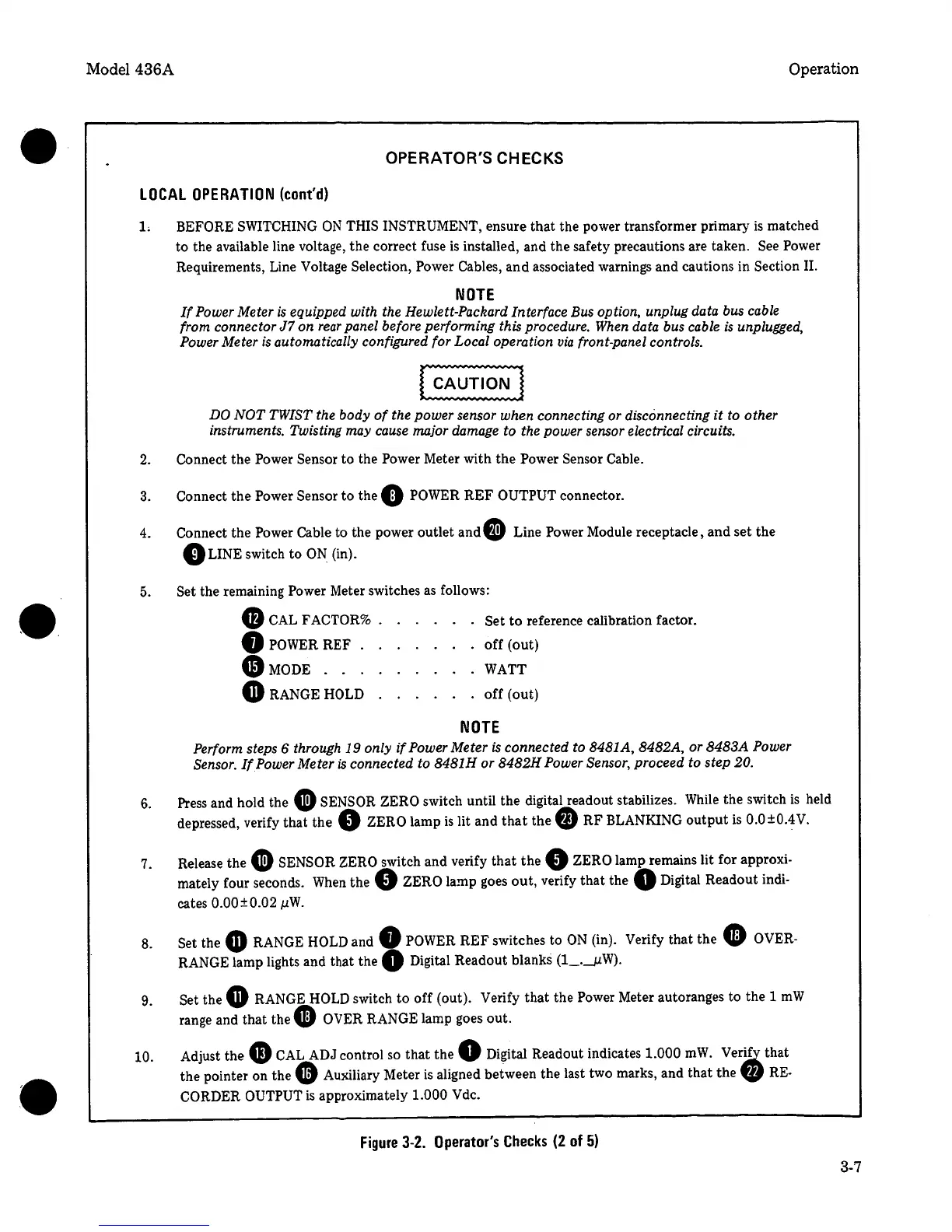
OPERATOR'S CHECKS
LOCAL
OPERATION
(cont'd)
1.
BEFORE SWITCHING
ON
THIS INSTRUMENT, ensure
that
the power transformer primary
is
matched
to the available line voltage,
the
correct fuse
is
installed, and the safety precautions are taken. See Power
Requirements, Line Voltage Selection, Power Cables,
and
associated warnings and cautions in Section II.
NOTE
If
Power Meter
is
equipped with the Hewlett-Packard Interface Bus option, unplug data bus cable
from connector
J7
on
rear
panel before performing this procedure. When data bus cable
is
unplugged,
Power Meter
is
automatically configured for Local operation
via
front-panel controls.
DO
NOT
TWIST
the body
of
the power sensor when connecting or disconnecting
it
to other
instruments. Twisting may cause major damage
to
the power sensor electrical circuits.
2.
Connect the Power Sensor to the Power Meter with
the
Power
Sensor Cable.
3. Connect
the
Power Sensor
to
the
0
POWER
REF
OUTPUT
connector.
4.
Connect the Power Cable
to the power outlet and
G)
Line Power Module receptacle, and
set
the
0
LINE switch to
ON.
(in).
5 .
6.
7.
8.
9.
10.
Set the remaining
Power
Meter switches as follows:
G
CAL FACTOR% Set
to
reference calibration factor .
•
POWER REF .
off
(out)
G)MODE
. . . WATT
GRANGE
HOLD
off
(out)
NOTE
Perform steps 6 through
19
only
if
Power Meter
is
connected to 8481A, 8482A, or
8483A
Power
Sensor.
If
Power Meter
is
connected to 8481H
or
8482H
Power Sensor,
proceed to step
20.
Press and hold the
G
SENSOR
ZERO
switch until the digital readout stabilizes. While the switch
is
held
depressed, verify that
the
0
ZERO
lamp
is
lit
and
that
the
fD
RF
BLANKING
output
is
0.0±0.4V.
Release the
G
SENSOR
ZERO
switch and verify
that
the
0
ZERO lamp remains lit for approxi-
mately four seconds.
When
the
0
ZERO
lamp goes
out,
verify
that
the
Q
Digital Readout indi-
cates
0.00±0.02
µW.
Set the •
RANGE
HOLD
and
0
POWER
REF
switches to
ON
(in). Verify that the
• OVER-
RANGE lamp lights and that
the
0
Digital Readout blanks (1_.__µW).
Set
the
G
RANGE
HOLD
switch
to
off
(out). Verify
that
the Power Meter autoranges to the 1
mW
range and
that
the
9
OVER
RANGE lamp goes
out.
Adjust the
G)
CAL
ADJ control so
that
the
0
Digital Readout indicates
1.000
mW.
Ver~
that
the pointer on the
•
Auxiliary Meter
is
aligned between the last two marks, and
that
the
'41
RE-
CORDER OUTPUT
is
approximately
1.000 Vdc.
Figure
3-2.
Operator's
Checks
(2
of
5)
3-7
 Loading...


