Model
436A
Operation
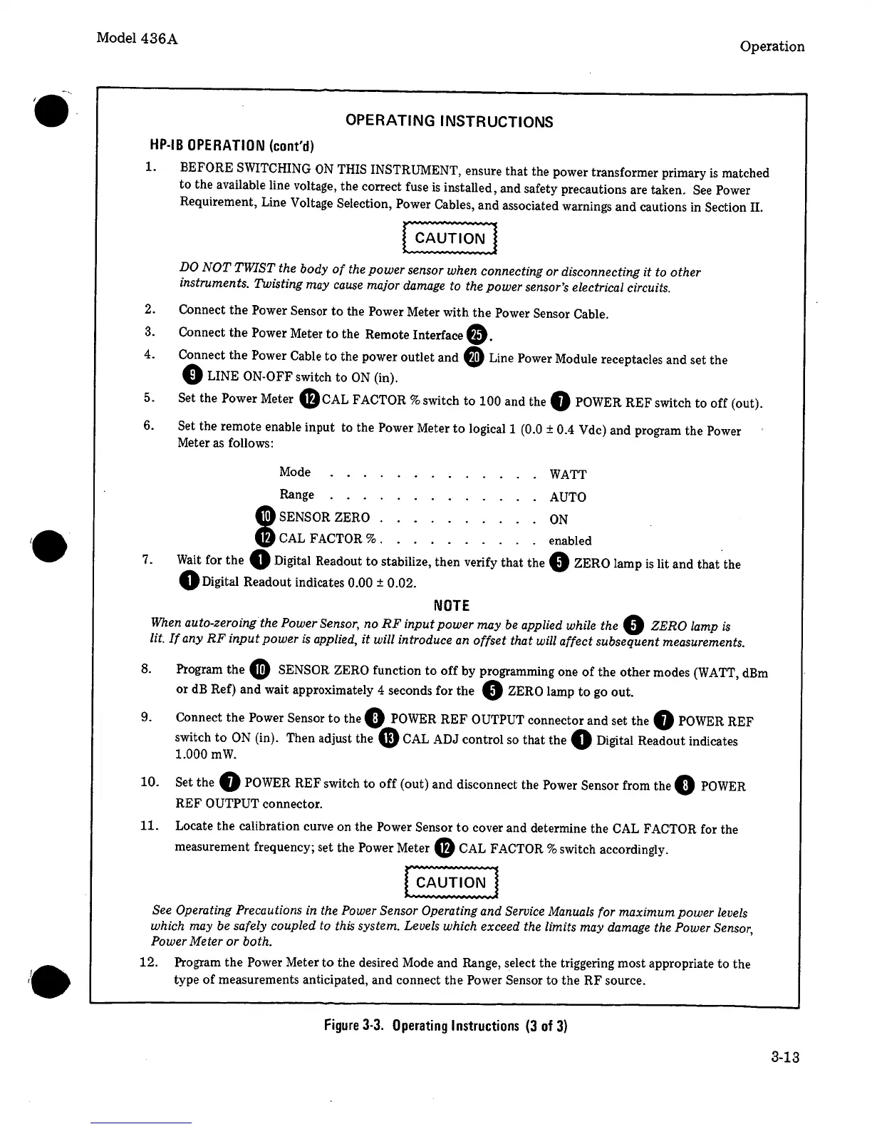
OPERATING INSTRUCTIONS
HP-IB
OPERATION
(cont'd)
1.
BEFORE
SWITCHING
ON
THIS INSTRUMENT, ensure that the power transformer primary
is
matched
to
the available line voltage, the correct fuse
is
installed, and safety precautions are taken.
See
Power
Requirement, Line Voltage Selection, Power Cables, and associated warnings and cautions in Section II.
DO
NOT
TWIST
the body
of
the power sensor when connecting or disconnecting it to other
instruments. Twisting may cause major damage to the power sensor's electrical circuits.
2. Connect
the
Power Sensor
to
the Power Meter with
the
Power Sensor Cable.
3.
Connect
the
Power Meter
to
the Remote Interface
8-
4.
Connect the Power
Cable
to
the power outlet and
@
Line Power Module receptacles and set the
0
LINE
ON-OFF
switch to
ON
(in).
5.
Set the Power Meter
f)cAL
FACTOR%
switch
to
100
and the
f)
POWER
REF switch
to
off (out).
6.
Set the remote enable input to the Power Meter
to
logical
1
(0.0
±
0.4 Vdc)
and program the Power
Meter
as
follows:
7.
Mode . . . .
WATT
Range . . . .
AUTO
G)sENSOR
ZERO .
ON
$
CAL
FACTOR
%
. enabled .
Wait
for the
0
Digital Readout
to
stabilize, then verify that the
0 ZERO
lamp
is
lit and that the
0
Digital Readout indicates
0.00
±
0.02.
NOTE
When auto-zeroing the Power Sensor, no
RF
input power may
be
applied while the
0
ZERO
lamp
is
lit.
If
any
RF
input
power
is
applied,
it
will introduce
an
offset
that will affect subsequent measurements.
8.
Program the
G)
SENSOR ZERO function
to
off
by programming one
of
the other modes
(WATT,
dBm
or
dB
Ref) and wait approximately
4
seconds for the
0
ZERO
lamp
to
go
out.
9.
Connect the Power Sensor
to
the
0
POWER
REF
OUTPUT
connector and set the
f)
POWER
REF
switch
to
ON
(in). Then adjust the
G
CAL
ADJ control
so
that the
0
Digital Readout indicates
1.000
mW.
10.
Set the
G
POWER
REF switch
to
off
(out) and disconnect the Power Sensor from the
0
POWER
REF OUTPUT
connector.
11. Locate the calibration curve on the Power Sensor
to
cover and determine the
CAL
FACTOR
for the
measurement frequency; set the Power Meter
f)
CAL FACTOR%
switch accordingly.
See Operating Precautions in the Power
Sensor
Operating and
Service
Manuals for maximum power levels
which may be safely coupled to this system. Levels which exceed the limits may damage the Power Sensor,
Power
Meter or both.
12. Program the Power Meter
to
the desired Mode and Range,
s_elect
the triggering most appropriate to the
type
of
measurements anticipated, and connect the Power Sensor to the
RF
source.
Figure
3-3.
Operating
Instructions
(3
of
3)
3-13
 Loading...


