Performance Tests
Model 436A
PERFORMANCE TESTS
4-12.
CALIBRATION
FACTOR TEST
SPECIFICATION:
16-position switch normalizes meter reading to account for calibration
factor. Range
85%
to
100%
in 1
% steps.
100% position corresponds
to
calibration factor
at
50
MHz.
DESCRIPTION:
PROCEDURE:
4-6
After
the
Power
Meter is zeroed on
the
most
sensitive range, a 1
mW
input
level is ap-
plied
to
the
Power Meter and
the
CAL
ADJ
control is adjusted
to
obtain a
1.000
mW
indication. Then
the
CAL FACTOR
% switch
is
stepped through its
16
positions
and
the
digital readout is monitored
to
ensure
that
the
proper indication is obtained for
each position.
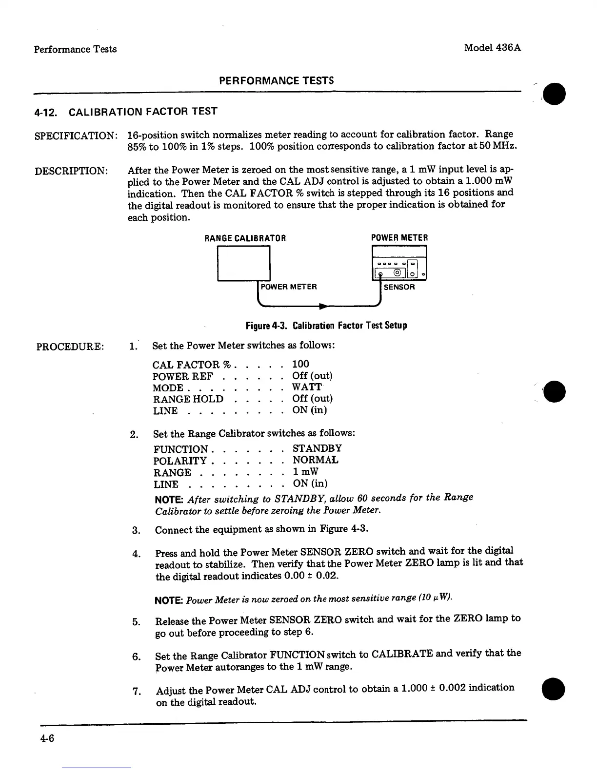
RANGE
CALIBRATOR
POWER
METER
000@1~
0
e-OWER METER
-
SENSOR
-
Figure
4-3.
Calibration
Factor
Test
Setup
1.
Set
the
Power
Meter switches
as
follows:
CAL FACTOR %
.
POWERREF
.
MODE
....
RANGE HOLD
LINE
....
100
Off
(out)
WATT
Off
(out)
ON
(in)
2.
Set
the Range Calibrator switches as follows:
FUNCTION
.
STANDBY
POLARITY.
NORMAL
RANGE
.
.
lmW
LINE . . .
ON
(in)
NOTE:
After
switching
to
STANDBY,
allow
60
seconds for the
Range
Calibrator
to
settle before zeroing the
Power Meter.
3. Connect
the
equipment
as
shown in Figure 4-3.
4. Press and hold
the
Power Meter
SENSOR ZERO
switch
and
wait for
the
digital
readout
to
stabilize. Then verify
that
the
Power
Meter
ZERO
lamp
is lit and
that
the
digital
readout
indicates
0.00
±
0.02.
NOTE:
Power
Meter is now zeroed on the most sensitive range
(10
µ.
W).
5. Release
the
Power
Meter
SENSOR ZERO
switch and wait for
the
ZERO
lamp
to
go
out
before proceeding
to
step 6.
6.
Set
the
Range Calibrator FUNCTION
switch
to
CALIBRATE
and
verify
that
the
Power
Meter autoranges
to
the
1
mW
range.
7. Adjust
the
Power
Meter
CAL
ADJ control
to
obtain a
1.000
±
0.002
indication
•
on
the digital readout.
 Loading...


