Adjustments
Model 436A
ADJUSTMENTS
5-17. AUTO ZERO OFFSET ADJUSTMENT
(cont'd)
EQUIPMENT:
PROCEDURE:
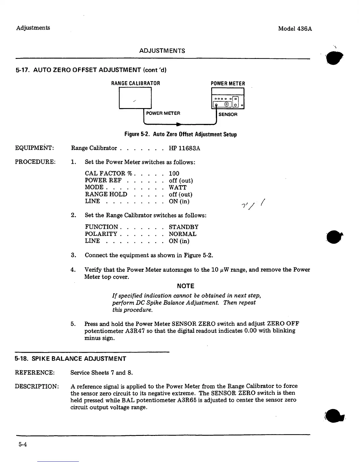
RANGE
CALIBRATOR
POWER
METER
/
000@1~0
l
POWER
METE~
SENSOR
-
Figure
5-2.
Auto
Zero
Offset
Adjustment
Setup
Range Calibrator . . . . . . .
HP
11683A
1.
Set
the
Power
Meter switches as follows:
CAL FACTOR
% .
POWERREF
.
MODE
....
RANGE
HOLD
LINE
....
100
off
(out)
WATT
off
(out)
ON
(in)
2. Set
the
Range Calibrator switches
as
follows:
FUNCTION.
POLARITY.
LINE
...
STANDBY
NORMAL
ON (in)
3. Connect
the
equipment
as
shown in Figure 5-2.
4. Verify
that
the
Power
Meter autoranges to
the
10
µW
range,
and
remove
the
Power
Meter
top
cover.
NOTE
If
specified indication cannot
be
obtained in
next
step,
perform DC Spike Balance Adjustment. Then repeat
this procedure.
5.
Press
and
hold
the
Power Meter SENSOR ZERO
switch and adjust
ZERO
OFF
potentiometer A3R4
7 so
that
the
digital readout indicates
0.00
with blinking
minus sign.
5-18.
SPIKE
BALANCE
ADJUSTMENT
REFERENCE:
DESCRIPTION:
5-4
Service
Sheets
7 and
8.
A
reference signal
is
applied
to
the
Power Meter from
the
Range Calibrator
to
force
the
sensor zero circuit
to
its negative extreme. The SENSOR ZERO
switch is
then
held pressed while BAL potentiometer A3R65 is adjusted
to
center
the
sensor zero
circuit
output
voltage range.