If the voltmeter reading is within the limits, the A50 +5 VD power supply is veried.
Turn the analyzer power o and reconnect the cable to the A50J3. Then continue with
the next
Disconnect Cables on the A1 CPU
section.
3. Disconnect Cables on the A1 CPU
a. Turn the analyzer power o.
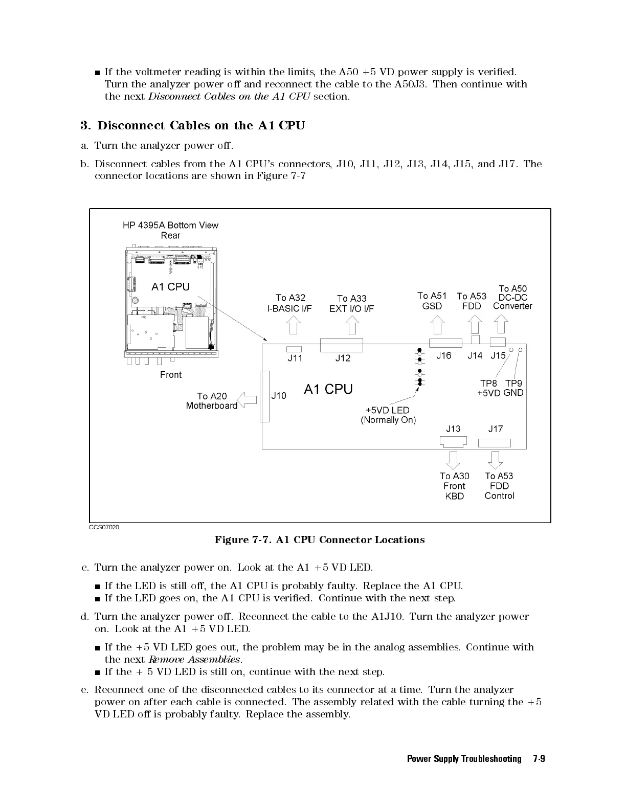
b. Disconnect cables from the A1 CPU's connectors, J10, J11, J12, J13, J14, J15, and J17. The
connector locations are shown in Figure 7-7
Figure 7-7. A1 CPU Connector Locations
c. Turn the analyzer power on. Look at the A1 +5 VD LED
.
If the LED is still o, the A1 CPU is probably faulty
. Replace the A1 CPU.
If the LED goes on, the A1 CPU is veried. Continue with the next step.
d. Turn the analyzer power o. Reconnect the cable to the A1J10. Turn the analyzer power
on. Look at the A1 +5 VD LED.
If the +5 VD LED goes out, the problem may be in the analog assemblies. Continue with
the next
Remove Assemblies
.
If the + 5 VD LED is still on, continue with the next step.
e. Reconnect one of the disconnected cables to its connector at a time
. Turn the analyzer
power on after each cable is connected. The assembly related with the cable turning the +5
VD LED o is probably faulty. Replace the assembly.
Power Supply Troubleshooting 7-9
 Loading...


