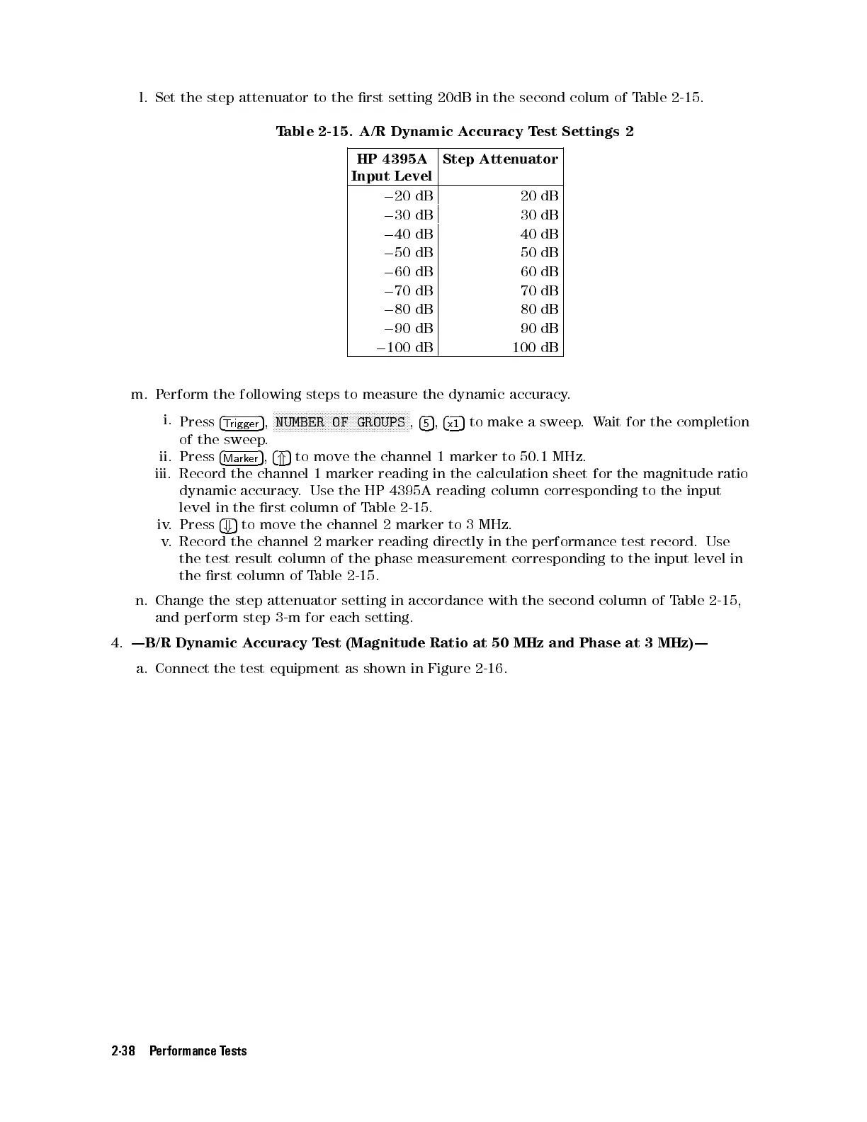
l. Set the step attenuator to the rst setting 20dB in the second colum of Table 2-15 .
Table 2-15. A/R Dynamic Accuracy Test Settings 2
HP 4395A
Input Level
Step Attenuator
0
20 dB 20 dB
0
30 dB 30 dB
0
40 dB 40 dB
0
50 dB 50 dB
0
60 dB 60 dB
0
70 dB 70 dB
0
80 dB 80 dB
0
90 dB 90 dB
0
100 dB 100 dB
m. Perform the following steps to measure the dynamic accuracy.
i.
Press
4
Trigger
5
,
NNNNNNNNNNNNNNNNNNNNNNNNNNNNNNNNNNNNNNNNNNNNNNNNNN
NUMBER OF GROUPS
,
4
5
5
,
4
x1
5
to make a sweep.Wait for the completion
of the sweep.
ii. Press
4
Marker
5
,
4
*
5
to move the channel 1 marker to 50.1 MHz.
iii. Record the channel 1 marker reading in the calculation sheet for the magnitude ratio
dynamic accuracy. Use the HP 4395A reading column corresponding to the input
level in the rst column of Table 2-15.
iv. Press
4
+
5
to move the channel 2 marker to 3 MHz.
v. Record the channel 2 marker reading directly in the performance test record. Use
the test result column of the phase measurement corresponding to the input level in
the rst column of Table 2-15.
n. Change the step attenuator setting in accordance with the second column of T
able 2-15 ,
and perform step 3-m for each setting.
4.
|B/R Dynamic Accuracy Test (Magnitude Ratio at 50 MHz and Phase at 3 MHz)|
a. Connect the test equipment as shown in Figure 2-16.
2-38 Performance Tests
 Loading...


