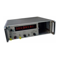
Model 5245L
Table 6-4. Povrer
Supply Voltages
Test
Point
Line
Voltage
Adjustment
103
115
t27
A6(15
)
A6(12)
A7(13)
A7(4)
A16(11)
A7(B)
A?(10)
-120
xlT1a
+160
r10%
-
15
t.5
+
13
t.5
+ 20
t.5
-6.9
+
1
+1?.6
+
1
-130t 1070
+
1?0
+
lj7o
-
15
t.5
+
13
t.5
+
20t.5
-6.9
r
1
+17.6
t
1
-150
xlT7o
+180
+107o
-
15
t.5
+
13
+.5
+
20
t.5
-6.9
*
1
+17.6
+
1
None
None
R5
Rl2
Rl?
Depends
on
adjustment
of
+20vdc
and
-1Svdc
above
6.19. INPUT AMPLIFIER A19.
6-20.
The
following
procedure
sets
the output
level
and checks
the
gain,
frequency response,
and sensi-
tivity of the
input
amplifier.
a.
Turn counter
on and set
L
E V
E
L
to
PRESET.
b.
With no input connected,
measure the
output
dc
voltage
at A19(6).
c. Adjust dc voltage with A19R20 to
+6.3V
+. 2V.
d.
Connect
outputof
Test
Oscillator
to
Counter
DC
INPUT
connector
with 50-ohm
termination
at Counter.
e.
Set Test Oscillator output to 50
MHz
at
100
mV
rms.
f. Check output
at A19(6) with Oscilloscope;
output
should
be 1.5V
p-p
minimum.
g.
Increase
output
of Test
Oscillator
to
3V rms.
Theoutput
at .4'19(6) is asymmetrically
clipped
wave-
form approximately
2V
p-p.
h. Set SENSITIVITY
to
.1V,
TIME
BASE to
10
ms,
and
FIJNCTION to
FREQUENCY.
i.
Set Test
Oscillator output
to
50 MHz
at 100
mV
rms.
j.
AdjustA19R20
until correct count
appears.
Re-
duce
input
signal
amplitude and readjust
A19R20
for
mu<imum sensitivity.
6-2
1.
6-22.
Change
RATIO
INPUT AMPLIFIER
A2O.
Repeat steps
a through
g
in
Paragraph
6-20.
A19(6) to
A20(6).
Section VI
Paragraphs
6-19
to
6-33
b. Conneet
output
of Test Oscillator 50
MHz
at
100
mV to Counter EXT. TIME BASE through
50-ohm
termination.
c.
Adjust
A20R20
until
correct
count
appears.
Re-
duce
input
signal
amplitude
and
readjust
A20R20
for
maximum
sensitivity.
6-23.
FUNCTION
CONTROL
A21
a.
Set TIME BASE
to.1
prs
and
FUNCTION to
1
PERIOD
AVERAGE.
b. Set
Test Oscillator to
1.5
MHz
at 100
mV and
connect to the
Counter
AC SIGNAL
INPUT
connector.
c.
Observe correct
count on
counter.
Reduce
the
Test Oscillator output
and adjust
A21R31 for
maximum
sensitivity.
Note
Do not
change the setting
of the
output
Ievel control
A19R20.
6-24.
TROUBLESHOOTI
NG.
6-25.
TROUBLESHOOTING
AIDS.
6-26.
OPERATING
MANUAL. The Operating
Manual
provided
with the HP 5245L
provides
general
informa-
tion
about the
instrument
and its capabilities.
Refer
to
the Operating
Manual for
specifications,
installa-
tions, step-by-step
operating
procedures,
and a
quick
operator's
check of instrument operation.
6-27.
PRINCIPLES
OF
OPERATION. SectionII
pro-
vides valuable information on
how
the
instrument
and
its circuits function.
6-28. SCHEMATIC DIAGRAMS.
Schematic
diagrams
and
a
block diagram
are
provided
in Section
Vtr.
6-29. COMPONENT
LOCATION.
Photographs
are
provided
with the schematic
diagrams
to
aid in
lo-
cating components on switches
or
circuit boards.
6-30. TROUBLESHOOTING
"T
R E E".
A step-by-
step
troubleshooting
procedure
is
provided
on
pages
6-10 through
6-13. This
procedure
is based
on the
self
check feature of the
instrument
and makes
max-
imum
use of front
panel
controls
and indicators.
6-31. SELF CHECK TABLES.
Table
6-8
provides
33 unique combinations of
Go-No Go situations
pos-
sible
in the
Self Check function.
Circuit elements
to
be
checked are indicated
for each combination.
Table
6-6 lists assemblies checked
in
Self Check
functions.
6.32. TROUBLESHOOTING
PROCEDURE.
6-33.
MALFUNCTION AT
TURN ON. If counter
fails
to turn on
(no
display,
decimal
point,
or
measurement
units) make the following checks:
a.
Line
voltage switch set
for
power
source.
b.
Power
cord
plugged
into counter
and
power
source.
c.
Line
fuse
good.
d.
Ac
power
available
at
source.
e.
Power
supply
(.4,6,
A7,
T2,
L1, L2,
C5).
6-3
a.
Set SIGNAL
INPUT SENSITIVITY to 1V
range,
TIME BASE to
EXT., AIID
FIINCTION to 1
PEzuOD
\
AVERAGE. SCt OUTPUT
STANDARD
FREQUENCY
(rear
panel)
to 100
Hz. Connect
a coaxial
cable
from
OUTPUT STANIDARD
FREQUENCY
(rear
panel)
to
AC
SIGNAL INPUT
(front
panel).
02349-1

 Loading...