Model
5245L
Section
fI
Paragraphs 2-1
to
2-10
sEcTtoN il
PRINCIPTES
OF
OPERATION
2.I.
INTRODUCTION.
2-2.
This
section
describes horv
the
Model
5245L
operates.
Basic circuitsused
in
the
counter
are des-
cribed
first
(Paragraphs
%3
through
2
-24).
Operation
of decimal counters and decade dividers
is
thoroughly
discussed
in Paragraphs 2-25
through
2-35.
A
dis-
cussionof basic counter
functions isgiven next(Para-
graphs
2-36 through 2-43).
Pulse
timing
circuits
and
overall operation of
the entire counter
are discussed
in Paragraphs
2-44 through
2-50.
At
the end
of the
section each
assembly is described in order of
its
assembly designation
(A
)
(Paragraphs
2-51
through
2-L22.
)
-
2-3.
THE
DIODE.
2-4.
GENERAL.
Semiconductor diodes are
used in
signal-handling
circuits and in
pover
supply
rectifier
and regulator circuits.
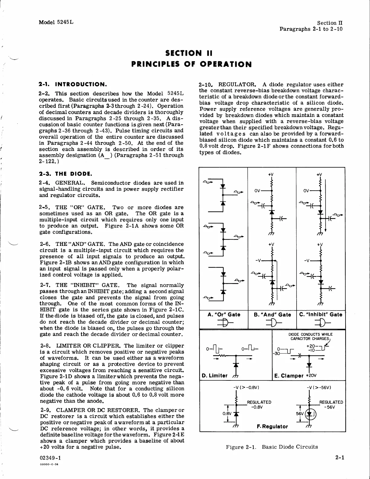
2-5.
THE
"OR"
GATE.
TVo or more
diodes are
sometimes
used
as
an OR
gate.
The OR
gate
is a
multiple-input circuit
which requires
only one
input
to
produce
an output. Figure 2-1A
shorvs
some
OR
gate
configurations.
2-6. THE
"AI.ID"
GATE.
The AI.ID
gate
or coincidence
circuit
is
a multiple-input circuit
which
requires the
presence
of all input
signals to
produce
an output.
Figure
2-18
shows
anANDgate
configuration
in
which
an
input
signal
is
passed
only
when a
properly
polar-
ized control
voltage
is
applied.
2-7.
THE
"INHIBII"
GATE.
The signal
normally
passes
through an INHIBIT
gate;
adding
a second signal
closes
the
gate
and
prevents
the
signal
from
going
through. One
of
the most
common
forms of the
IN-
IIIBIT
gate
is
the
series
gate
shown
in Figure
z-LC.
If
thediode
is
biased offrthe
gate
is
closed,
and
pulses
do
not reach
the decade
divider or decimal counterl
when
the diode is biased on,
the
pulses
go
through
the
gate
and reach
the
decade
divider or
decimal
counter.
2-8. LIMITER OR CLIPPER.
The
limiter or clipper
is a circuit
which
removes
positive
or negative
peaks
of
waveforms.
It can
be used either as a waveform
shaping
circuit
or
as
a
protective
device
to
prevent
excessive
voltages
from
reaching a
sensitive
circuit.
Figure 2-1D
shonrs a
limiterwhich
prevents
the
nega-
tive
peak
of a
pulse
from
going
more
negative than
about
-0.
6
volt.
Note
that for a conducting silicon
diode the
cathode
voltage
is
about
0.6
to
0.8 volt
more
negative
than the
anode.
2-9. CLAIVIPER OR DC
RESTORER.
The clamper
or
DC restorer
is
a circuit
which establishes
either the
positive
ornegative
peakof
awaveformat a
particular
DC reference voltagel
in other
words,
it
provides
a
definite
baseline
voltage f or the
wavef
orm.
Figure
2-1E
shols
a
clamper
which
provides
a baseline
of about
+20
volts
for a negative
pulse.
02349-1
2-10,
REGULATOR. A diode regulator uses
either
the
constant reverse-bias
breakdonrn voltage
charac-
teristic of a breakdown diodeorthe constant fonpard-
bias voltage drop characteristic
of a
silicon
diode.
Power
supply
reference
voltages are
generally pro-
vided
by breakdorpn
diodes
which
maintain a
constant
voltage
when supplied
with
a
reverse-bias
voltage
greater
than
their
specified
breakdorpn voltage.
Regu-
Iated
voltages can
also
be
provided
by a
fonvard-
biased
silicon
diode
which
maintains a
constant
0.6
to
0.8volt
drop. Figure 2-1F
shorps
connections
forboth
types of diodes.
A.
"Or"
Gate
D-
B.
"And"
Gatg
+
C.
"lnhibit"
Gate
s_
D.
Limiter
E.
Clampel
+2oV
-v
(>
-0.8v) -v
(>-s6v)
REGULATED } REGULATED
ry-s6v
-o.8v
F.
Regulator
Figure 2-1.
Basic
Diode Circuits
2-L
 Loading...


