EasyManua.ls Logo

HP 5245L - Page 121

HP 5245L
270 pages
To Next Page IconTo Next Page
To Previous Page IconTo Previous Page
Loading...
Section
VI
Figure
6
-z
Model
5245L
02349
-L
o5245-B-il
2,3
tr
ufr
1.
6.
SAIVIPLE
RATE
a.
Controls
pover
to
aII
circuits except
crystal
oven heater; max cs\rr
turns
PCIMER
OFF.
b.
Controls
time between
measurements
from
0.2
sec to
5
sec.
c. Causes display to
HOLD indefinitely
when
murimum
g\p.
DC
SIGNAL
INPUT
provides
direct coupling
to
internal
amplifier
for most measurements.
AC SIGNAL
INPIIT
provides
coupling to
internal
amplifier
through
.022
ltt
(600
vdc
maximum).
SIGNAL
INPUT
SENSITIVITY
&
LEVEL control.
&.
Controls
input
attenuator; set to
highest
pos-
ition
which
includes
signal
amplitude
(max
overload;
50v in
position
0.
1,
150v
in
posi-
tion
1
;
500v
in
position
10).
b.
Ma;rimum CCW
(CHECK
position)
gives
in-
ternal self
check;counts
10
MHz
with selected
TIME-BASE
gate
for FREQUENCY;100
kHz
for
number of
periods
averaged
(10
psec
to
1
sec)
for
PERIOD
A\IERAGE,
or
contin-
uously at selected TIME
BASE
frequency
(0.
1Hz
to 10 MHz)
for
MANUAL START.
c.
Murimum CW
(PLUG-IN
position)
connects
outputof
plug-inunit
directly to
input
amplif
ier.
d.
The
LEVEL
control
adjusts the
input
trigger
level
from
-0.
3V
dc to
+0. 3V
dc when
atten-
uator
is
set
at
0.
1V rms, from
-3.0V
dc to
+3.0Vdc
when
attenuator
is
set
at
1V
rmgr
and
-30V
dc to
+30V
dc
when
attenuator
is
set
at
10V
rms.
e.
Maximum counterclockrvise
position
(PRE
-
SET)
sets
trigger
level
at
zero
volts.
GATE
lamp
glows
during
counting
(main
gate
open).
EXT
connector
a. Provides input
for higher
of
two
frequencies
for ratio
measurement
(Iorver
frequency
to
SIGNAL
INPUT)
when
TIME
BASE
set
to
EXT.
b,
Provides
output frequency
0.
1 Hz
to
1
MHz
as
selected
by
TIME-BASE
switch
(see
text
for
re
strictions)
.
TIME
BASE
selects
either time
that
main
gate
is
on
for
frequency
or
time unit
per
count for
period
measurement.
B.
RESET
pushbutton
returns
both displayed
and
internal
count
to zero
when
pressed.
9. FI]NCTION
a. Permits
totalizing of
pulses
applied
to SIG-
NAL
INPUT
when set
to
MANUAL
START;
holds
accumulated
count
when switched to
MANUAL
stop.
b.
Permits
measurement
of frequency
applied
to SIGNAL
INPUT
during interval
selected
by TIME-BASE
switchwhen in FREQUENCY.
c.
Permits
period
measurement
of
waveforms
applied
to
SIGNAL INPUT averaged
over
1
to 100,000
periods
when
set
to
PERIOD
AVERAGE.
d. Removes
control of TIME-BASE
and FUNC-
TION
switches
when
set to REMOTE or TIME
INT;
remote
control is
provided
through
rear
connector
or
plug-in
unit.
2.
3.
4.
7.
6-6
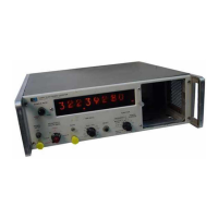
Figure
6
-2.
Operating
Controls
(Front
Panel)

Other manuals for HP 5245L

Related product manuals