Table
2-1. Four-Line
Code Truth Table
Digit
4-Line code,
|
=
ilBgftlT""
Sfftrf
D c B A
0
1
2
3
4
5
6
1
8
I
0
0
0
0
0
0
1
1
1
1
0
0
0
0
1
1
1
1
1
1
0
0
1
1
1
1
0
0
1
1
0
1
0
1
0
1
0
1
0
1
Model
5245L
2-31.
Waveforms
showing time
relationships
for
the
counter
are
given
in
Section VII;
remember that a
driven
binary
switches only when
the
input
wave
is
going
positive.
(Diode
clipping
removes
negative
por-
tion of input).
2-32. ELECTRICAL
READOUT.
A
four-line
binary-
coded-decimal
output is
available from
each
decimal
counter
assembly. A
voltage representing the state
of
each binary is
taken from
the collector
of each of
the
plain-Iettered
transistors
(A,
B,
C,
and
D).
A
binary
"9"
is represented
by a relativelypositive
volt-
age on
each
line, and
a binary
"0"
is represented
by
a relatively negative
voltage on each line. Table
2-1
summarizes
the ten
allowable combinations
which
represent the decimal
digits
"0"
through
"9".
To
protect
the binary
circuit
from
being affected
by the
load,
each output line includes
a
100K
ohm series-
connected isolation
resistor.
Section
II
Paragraphs 2-31 to 2-35
(several
megohms)when dark and a relativelylow re-
sistance
element
(less
than
?000 ohms)
when
illumin-
ated.
Thus
when the
three
photocell
elements
which
constitute
a circuit
path
are
illuminated,
resistance
drops to
about
201000
ohms
and
sufficient
current can
florv to
light
the
display
digit. Illuminating
elements
forthe
photocells
are
neon
lamps,
one of
which
is
con-
nected in
the
collector
circuit of
each
of
the eight
transistors
in
the
counting circuit; the
lamp lights
when the transistor
conducts.
As
explained
in Para-
graph
2.-30, a four-binary
counting circuit
has
ten
states,
ten combinations
of
conducting
and
noneonduct-
ing
transistors,
each
combination corresponding
to
one digit.
Thus
there
is
a
pattern
of
lighted lamps
for each digit. Assigrring
a binary
weight
of
1
when
the
plain-letter
lamp
(A,
B, Cr oJ
D) Iighls, and a
weight
of 0
when
the bar
lamp
(4,
E, e, or
D) tigtrts,
the
lamp
pattern
for any digit can be determined
from
Table 2-1.
Figure
?-9
shows the
countingcircuit
with
transistors
D, C,
-B,
A conducting. The
lamps
as-
sociated with these
circuits
illuminate
the
photocell
elements
in
the
circuit
to the
digit
0
display.
2-35.
The
circuit sequence
required
to light a lamp
is discussed in the following
paragraphs.
The sequence
discussed
will
have
more meaning if itis remembered
1)
that a much highervoltageisrequiredto
fire a neon
Iamp
than to
maintain
illumination in the lamp
(for
the
lamps used in the Model 5245L,
?0
volts for
firing
and
55 volts for maintaining illumination), and 2) that
after application
of
the firing voltage the lamp
cannot
fire immediately
because
of the time required
for
ionization.
Arrangement
of the
binary
lamp
circuit
used in the Model
5245L
is indicated in Figure
2-88.
As will
be discussed
later, diodes
connected
between
the lamps make it
possible
for the
circuit
to
store
a
previous
count even
though the
binaries
are switching
during the next
counting
period.
In
decimal counter
assemblies
which do not have
this
storage
feature,
the display
changes
with
each
step the
binaries
take
in setting
up
the
circuit
for a
given
digit. To
clarify
certain
aspects of the lamp
circuit sequence,
the
lamp
circuit
wiII
first
be
discussed
as thoughtherewere no
diodes
between
the two lamps of a
binary;
this
circuit
is
shown
in Figure 2-8A.
a. Lamp
Circuit
without Diodes.
(1)
As
indicated
in
Figure
2-8A-1,
the
lamp
associated with the conducting
transistor
is
2-33.
DIGITAL
DISPLAY.
A
display
matrix, con-
sisting
of eight neon
input
lamps
and
18
photoconductive
elements
is used
to
convert
the binary-coded-repre-
sentation to a digital
representation. The display
matrix is
shown
in
the Decimal
Counter
schematics,
Figures
7-9,
7-ll, and
?-14.
2-34.
As
indicated in
the
schematic
diagrams,
Fig-
ures
7-9,
?-Ll,
andT-L4,
the circuit to each
nu-
meral
in
the display is
brought through three
series-
connected
photocell
elements. A characteristic
of the
photocell
element
is
that it
is
a
high
resistance
element
02349- 1
o5212-B-3
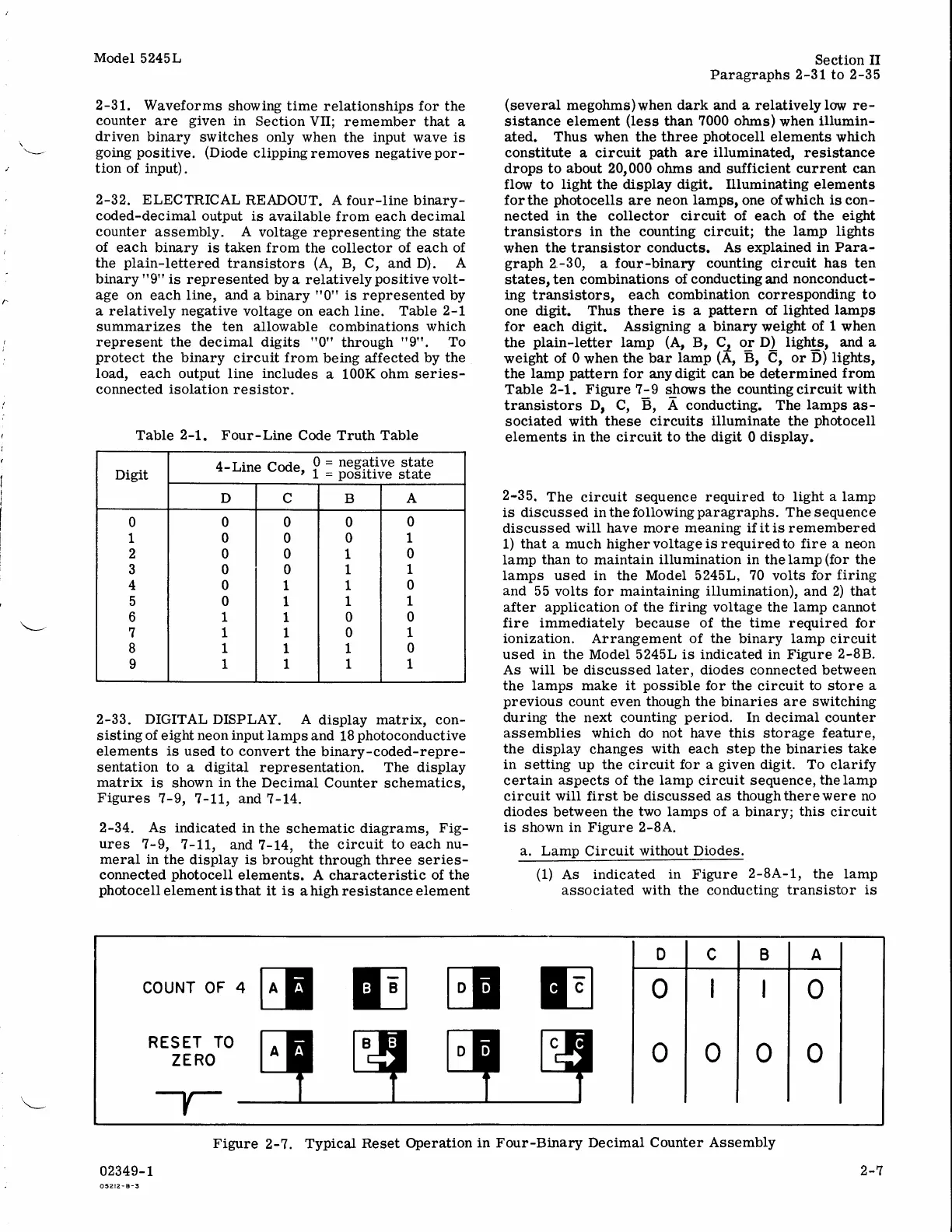
COUNT OF 4
RESET TO
ZERO
EEET
Figure
2-?.
Typical
Reset
Operation
in Four-Binary Decimal
Counter Assembly
2-7
 Loading...


