Model
5245L
-130volts.
Note
that the
-130volt
supplyis the source
for
shunt
regulator
A?CR2
which
provides
-56
volts
to
the
-15
volt regulator
circuit.
2-69.
+l3-VOLT
AND
+20-VOLT
SUPPLIES.
The
+13-volt
supply
(Q3,
A?Q3,
and A?Q4;
see schematic
Figure 7-7)
is
similar to
the
-15
volt
supply
des-
cribed in Paragraph
2-65.
The
only
significant
dif-
ference
is
that t}te
negative
leg is
grounded
while
the
positive
Ieg
provides
the regulated output. The
+20
volt
supplyis
obtained
by adding a Tvolt
source
to the
+13
volt
supply.
The
7 volt regulator
consists
of
Q4
and A?Q5, both
acting as
emitter
follorvers. A
?
volt
zener diode and
a
bias adjustment
circuit
provide
the
reference
voltage
for
this supply.
2-70. DECIMAL PON.{T
ASSEMBLY AB.
2-7L.
INPUT. The
decimal
point
assembly
holds
eight
neon
lamps
which
are located
to the
left of
each
digital display
tube on the front
panel.
Lamps
are
designated
0
through? from right
toleft
as seen
look-
ing
at the
front
panel.
The
decimal
point
control signal
consists of
+1
70
volts applied
to the
desired lamp
input.
Control is
suppliedeitherfromthe
TIME BASE switch
or
the
lower
REMOTE CONTROL
connector
on
the
rear
panel.
2-72. OUTPUT.
A
group
of OR
gates
converts
the
decimal
point
control
signal
from
decimal
form
to
binary-coded decimal
(BCD)
form
which
is supplied
to
the
DIGITAL
RECORDER
connector
on
the
rear
panel.
As an
example,
suppose decimal
point
5 is
Iighted;
a
positive
signal
passes
the
OR
gates
and
Iimiters
to
the A, B, and
C output lines,
thus
pro-
viding a
0111
(in
the order
DCBA) output
to the
DIGITAL
RECORDER
connector.
For circuit details
refer
to the
schematic diagram,
Figure
7-8.
2.73.
MEASUREMENT
I]NITS
ASSEMBLY A9.
2-74.
INPUT. The
measurement
units assembly
holds
six neon lamps
which
are
located on
the
front
panel
at
the right
end of
t}re counter display.
Lamps
aredesignated
MC, KC,
SEC,
mS,
pS,
and
*(asterisk).
As
with the
decimal
point
assembly,
the measurement
units control
signal consists
of
+170
volts applied to
the
desired lamp input.
Control is
supplied either
from
the
TIME-BASE
switch
or
the
lovrer REMOTE
CONTROL connector
on
the
rear
panel.
2-15.
OUTPUT.
A
group
of OR
gates
converts the
measurement
units
control
signal from
decimal
form
to BCD form,
just
as
is
done in
the
decimal
point
as-
sembly.
The digitwhich
is
printed
for
each
measure-
ment unit is
given
in
a
table along
with
the schematic
diagram,
Figure 7-8. Print
wheels
are
available
for
Hewlett-Packard
recorders
sothat the correct
meas-
urement units
symbol can be
printed
directly.
2-76.
LOW
FREQUENCY
pECTMAL
COUNTER
ASSEMBLY A1O-A14.
2-77. The
low-frequency
decimal
counter
is
shown
in Figure
2-t44.
Note
the
inclusion
of clipper
diodes
CR9
through CRl3
which
permit
only
positive
pulses
02349-1
Section
II
Paragraphs
2-69
to
2-82
to
be delivered
to
the
input
base of each transistor.
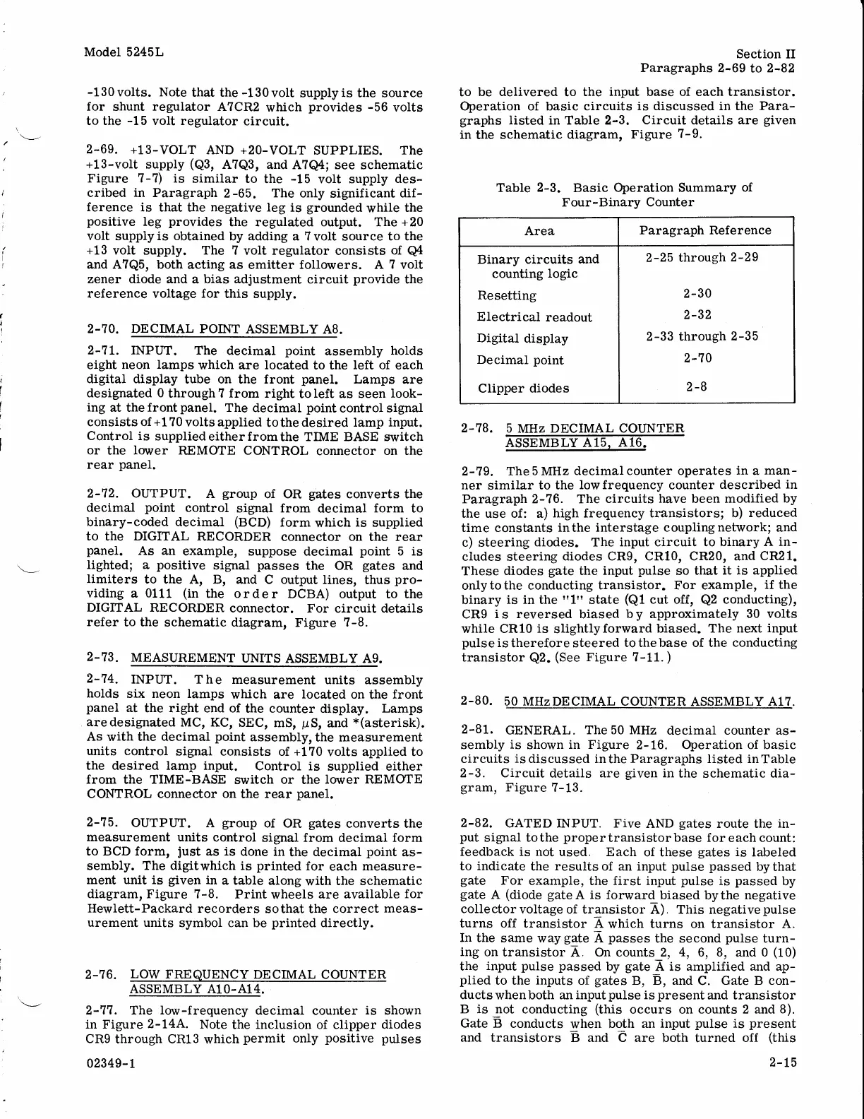
Operation of basic circuits
is discussed in
the
Para-
graphs
Iisted in Table 2-3. Circuit details
are
given
in
the
schematic
diagram,
Figure
7-9.
Table
2-3.
Basic
Operation Summary
of
Four-Binary Counter
2-78.
5
MHz DECIMAL
COIINTER
ASSEMBLY A15
A16
2-19. The
5 MHz
decimal counter operates
in
a
man-
ner
similar
to the lowfrequency counter
described
in
Paragraph 2-76. The
circuits
have
been
modified by
the use of: a)
high frequency
transistorsl b)
reduced
time constants
inthe interstage couplingnetwork; and
c) steering
diodes. The
input circuit to binary
A in-
cludes steering
diodes CRg, CR10, CR20, and
CR21.
These
diodes
gate
the
input
pulse
so
that
it is applied
only
to the
conducting
transistor. For example,
if the
binary
is in
the
"1"
state
(Q1
cut off,
Q2
conducting),
CRg
i
s
reversed
biased
b
y
approximately
30 volts
while CR10
is
slightlyforward
biased. The
next
input
pulseis
therefore steered
tothebase of the conducting
transistor
Q2.
(See
Figure
?-L1.
)
2-80.
50
MHzDECIMAL COUNTER
ASSEMBLY
A17.
2-81.
GENERAL.
The 50 MHz
decimal counter as-
sembly
is
shown
in Figure
2-16.
Operation of basic
circuits
isdiscussed
inthe Paragraphs listed inTable
2-3. Circuit
details are
given
in
the
schematic
dia-
gram,
Figure
7-13.
2-82.
GATED INPUT. Five
AND
gates
route
the
in-
put
signal tothe
propertransistorbase
for
each
count:
feedback is not
used. Each
of these
gates
is
labeled
to
indicate
the
results
of an input
pulse passed
bythat
gate
For
example, the
first input
pulse
is
passed
by
gate
A
(diode
gateA
is forward
biased bythe
negative
collectorvoltage
of transistor
A), This negativepulse
turns off
transistor A
which turns on
transistor
A.
In
the
same way
gate
A
passes
the second
pulse
turn-
ing
on
transistor
A.
On counts 2, 4,
6,
8,
and
0
(10)
the
input
pulse passed
by
gate
A
is
amplified
and
ap-
plied
to the
inputs
of
gates
B, B, and
C.
Gate B con-
ducts
whenboth
an
input
pulse
is
present
and
transistor
B is not
conducting
(this
occurs on
counts 2 and 8).
Gate
B conducts
when both
an
input
pulse
is
present
and
transistors B and e are
both turned
off
(this
Area
Paragraph
Reference
Binary
circuits
and
counting
logic
Resetting
Electrical
readout
Digitat
display
Decimal
point
Clipper
diodes
2-25 through
2-29
2-30
2-32
2-33 through
2-35
2-70
2-B
2-t5

 Loading...


