EasyManuals Logo

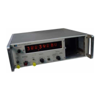
HP 5245L Service Manual

HP 5245L
270 pages
To Next Page IconTo Next Page
To Previous Page IconTo Previous Page
Page #30 background imageLoading...
Page #30 background image
Model
5245L
cable
leading
to
the trigger
on the function control
assembly
A21.
The
loaded
twisted
cable
optimizes
voltage
gain,
minimizes
capacity
effects, and
isolates
signal
ground
current.
See
Figure
7-1? for
circuit
details.
2-9L.
FUNCTION
CONTROL
ASSEMBLY
A21.
2-92.
GENERAL.
The function
control assembly,
Figure
2-17,
switches
the
counter logic
circuits
to
perform
the various
counting functions. The
signal
which
is
counted by
the
decimal
counting
assemblies
is
switched
to the high
frequency
trigger
by one of
the
input
gates;
1,
2,
4,
or 6. The
resulting
pulses
are
gated
by the
main
gate
and
then drive
the 50
MHz
DCA,
A1?.
The
signal
to control
the main
gate
is
switched
to
the
period
trigger by input
gates
3 or 5.
The re-
sulting
pulses
either
drivethe
gate
control
assembly,
M2
dftectly
through
gate
12 or
are divided by the
decade divider
assemblies
and
then
drive
the
gate
control
through
gate
13.
2-93.
SIGNAL
FLOW.
The following
outline
gives
signal
flow
for
each measurement
function. In
each
case the control
signal to
the
main
gate
is on
during
counting.
a.
MANUAL.
The input
signal
from
A19
passes
through
gate
2,
amplifier
Q1,
high frequency
trigger
Q3-Q4,
pulse
amplifier
Q9,
main
gate
Q10-Q11,
and
pulse
amplifier
Q13
to the
gated
signal
output.
b.
MANUAL
CHECK.
Same
a
s
MANUAL
except
gate
2 is
off
and
gate
1
is
on
so that
the
selected
fre-
Section
II
Paragraphs
2-91
to
2-93
quency
from
decade
dividers
passes
through
to
gated
signal output.
c. FREQUENCY.
Input
signal
path
same
as
f
o r
MA}{UAL.
Selected
frequency
passes
through
gate
3,
emitter follower
Q2,
period
trigger
Q5-e6,
and
gate
L2
to
the
gate
triggering
output.
d. FREQUENCY
CHECK.
Same
as for FREQUENCY
except
gate
2
is
off and
gate
6 is
on
so
that
a
10
MHz
signal
passes
to
gated
signal
output.
e.
PERIOD.
Selected frequency
from
the time
base
controlassemblyA3S
passesthrough
gate
1,
Ql,
trig-
ger
Q3'Q4,
Qg,
main
gate
Q10-Q11,
and
Q13
to the
gated
signaloutput.
The
input
signal fromQl9
passes
through
gate
5,
Q9,
period
trigger
Q10-q11,
and
gate
t2
to
the
gate
triggering
outputs.
f. PERIOD
CHECK. Same
as PERIOD
except that
gate
5 is
off and
gate
3 is
on
so that the selected
fre-
quency
(always
100
kHz for PERIOD
CHECK) from
the
time
base control assembly
A35
passes
to the
gate
triggering output.
g.
MULTI-PERIOD.
Same as PERIOD
except that
gate
12
is off
and
gate
13
is on.
The output
of
the
period
trigger
Q5-QO
is divided
by the
chain of
decade
dividers.
The
output
of the
proper
divider
drives the
multi-period
trigger
Q7-Q8,
and
passes
through
gate
13
to the
gate
triggering
output.
h. MULTI-PERIOD
CHECK.
Same as MULTI-
PERIOD
except
that
gate
5 is off
and
gate
3 is
on
so
02349-L
05 245 -B
-4
SIG.
INPUT
FROM AI9
GATED
SIG
TO
At7(2)
RATIO HF
INPUT
FROM
A2O
IOMHz
FROM
A35
GATING
SIG
FROM
A22(9)
SEL
FREO
TO
A2
SELECTED
FREQ
FROM
A35
MULTIPLIED
PERIOD
SIG WHEN
MULTI-PERIOD
AVE
FROM
A35
PERIOD
SIG
TO
A35
GATE
TRIGGERING
TO 422(8)
Qlo,Qil
MAIN
Figure
2-t7.
Function Control
Block Diagram
2-19

Other manuals for HP 5245L

Questions and Answers:

Question and Answer IconNeed help?

Do you have a question about the HP 5245L and is the answer not in the manual?

HP 5245L Specifications

General IconGeneral
BrandHP
Model5245L
CategoryCash Counter
LanguageEnglish

Related product manuals