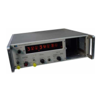
Model
5245L
5-1.
oPTloNs.
5-2.
The
5245L has two options
available.
They are
Option
02,
4-Iine BCD
7-2-4-8
"1"
state
positive
and
Option 03, 4-Iine BCD
1-2-4-8
"1"
state
negative.
These
options
change
the BCD
output code of the
digits.
The
decimal
point
and measurement
units
BCDoutput
code
is
l-2-2-4
r'ltr
state
positi've.
5-3.
OPTION 02 +1248
BCD
CODE.
5-4.
Option
02 consists
of
changing
the
assemblies
listed
in
Table
5-1.
Circuit
diagrams for
the
Option
02
assemblies are shown
in
Figures
7-10, 7-12, and
7
-15.
Table
5-1. Option
02 Replacement
Assemblies
5.5.
OPTION
03
-1248
BCD CODE.
Section V
Paragraphs
5-1
to 5-17
5-9. SPECIALS.
5-10. Decimal Point
and
Measurement
Units assem-
blies
with
either
"1"
state
positive
or negative
l-2-4-8
BCD output may
be obtained by
special
order. Speci-
fication
J35-5245L is a modified 5245L
that
provides
a
t-2-4-8
r'1r'
state
positive
BCD code
for
all eight
digits,
decimal
point
assembly, ild measurement units
assembly.
Specification J36-5245L is a
modified
5245L
that
provides
a
L-2-4-8
"1r'
state negativeBCD
code for
all
eight
digits,
decimal
point
assembly,
and
measurement
units
assembly.
5-11.
Circuit
diagrams
for
these specials
are
shown
in
Figures
5-1 and
5-2.
Parts
lists for
the specials
are listed in
Tables 5-B and 5-9.
5-L2. Remote
control operation is also available
by
special
order. Programming
information is covered
in
the
Model5245L
Operating Manual, Paragraphs 3-14
through
3-L7,
page
3-11. Circuit
diagram showing
additional wiring
is
shown
in Figure
5-3.
5-t3.
lmANUAt
CHANGES.
5-I4.
CURRENT
INSTRUMENTS.
5-15. This manual
appliesdirectlyto
standard
Model
5245L Electronic
Counter having
serial
prefix
num-
ber
628-
(refer
to
Paragraph
1-6).
5
-16.
OLDER INSTRUMENTS.
5-17. This
manual
covers
all
instruments
currently
available with
serial
prefix
628-.
As
instrument
changes
are made and this
manual
is revised,
back-
dating information
to cover
older
instruments
will
be
included
in
this
section. For instruments
with
serial
prefix
numbers
below
628-,
see
5245L
Operating and
Service Manual
prefixed
544-,
sEciloN v
OPTIONS
AND
'NANUAI
CHANGES
5-6. Option 03 consists
of
Iisted in
Table 5-2.
Circuit
03
assemblies
are shown
in
?
-16.
changing
the assemblies
diagrams
for the Option
Figures
7-10, 7-12, and
5-?. The
parts
listsfor
theOption02
and03
assemb-
lies
are
listed
in Tables
5-4,
5-5, 5-6,
and
5-7.
5-8. Figures
7-10
and 7-L2
are used
for both
Option
02 +1-2-4-8
BCD
output
and Option 03
-1 -2-4-g
BCD
output. The
boards
are
identical
with
one exception.
The
DCA's
with
"1"
state
positive
BCD
output
have
resistors
markedwith
a
double
asterisk
(**)
connected
to
collectors
as
shownby
+ +
Iines. The
DCA?s
with
"1"
state negative BCD
output have these
resistors
connecteci to
opposite
collectors
as
shown
by
-
lines.
Table 5-3.
1-2-4-8
Code Truth
Table
Digit
4-Line
Code,
l-2-4-8
D=B C=4 B=2 A= 1
0
1
2
3
4
5
6
7
B
I
0
0
0
0
0
0
0
0
1
1
0
0
0
0
1
1
1
1
0
0
0
0
1
1
0
0
1
1
0
0
0
1
0
1
0
1
0
1
0
1
Option 02: Output Code: 0
=
-BV, 1
=
+18V
Option 03: Output Code:
1
=
-8V,
0
=
+18V
Standard Assemblies
Option
02
Assemblies
A10-A14
DCA
52t2L-4A
A15-A.16
DCA05232-6010
A18 Readout 5245L-4B
A10-A14
DCA05212-6002
A15-A16
DCA05232-6002
A1B
Readout
05245-6001
Table
5-2. Option
03
Replacement
Assemblies
Standard
Assemblies
Option
03 Assemblies
A10-A14
DCA
52t2L-4A
A15-A16
DCA05232-6010
A18
Readout 5245L-48
A10-A14
DCA05212-6003
A15-A.16
DCA05232-6003
A18
Readout 05245-6003
02349-1 5-1

 Loading...