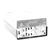
MANUAL CHANGES MODEL 5304A (05304-90006) Page
2
CHANGE
1
(1704A)
Page 9D-6-2, Table 9D-6-1,
A1
(05304-60001) Replaceable Parts:
>Add "SERIES
1704" to
Description
for A1
circuit board.
>Change
A1Q1 and A1Q2
from 05304-80001
to
1855-0213; DUAL JFET N-CHANNEL
2N5912; 28480; 1855-0213.
>Change
A1R19 and
A1R20 from 2100-1768 (20-ohm)
to
2100-2010; RESISTOR-VAR
COMP 10-ohm
20%;
32997; 3329H-1-10R.
. .•
Page 9D-8-5,
A1
(05304-60001) Schematic Diagram:
>Add "SERIES
1704" at top of A1
(05304-60001) schematic.
>Add "NOTE
4"
between A1Q1/A1Q3
and
A1Q2/A1Q4.
>Add
the
following under NOTES:
"4.
A1Q1/A1Q3
AND
A1Q2/A1Q4
ARE
DUAL JFET N-CHAN UNITS WITH.CENTER LEAD
TO
CASE CJJT
OFF."
>Change
Q1-4 in
TABLE
OF
ACTIVE COMPONENTS
to
Q1/Q3, Q2/Q4;
and HP
PART
NUMBER
to
1855-0213.
>Change
the
values
of A1R19 and
A1R20 from
20 to
10-ohm..
CHANGE
2
(1716A)
Page 9D-6-2, Table 9D-6-1,
A1
(05304-60001) Replaceable Parts:
>Change
A1
from series
1704 to 1716.
>Change
A1U15
from 1820-0077 (3N7474N)
to
1820-1112;
IC TTL LS
DUAL-D FLIP-
FLOP; 01295; SN74LS74N.
Page 9D-8-5. Figure 9D-8-1,
A1
(05304-60001) Schematic Diagram:
>Change series number,
at top of
diagram, from
1704 to 1716.
>Change
A1U15 in
TABLE
OF
ACTIVE COMPONENTS
to
1820-1112.
>Change
A1
schematic
by
disconnecting A1U15B(13) from
the
junction
of
U13E(10)
and
U8(1,10).
>Add
a
connection between A1U15B pins
12 and 13.
CHANGE
3
(1804A)
Page 9D-6-2, Table 9D-6-1,
A1
(05304-60001) Replaceable Parts:
>Change
A1
series number from
1716 to 1804.
>Change
A1R19 and
A1R20 from 2100-2010 (10-ohm)
to
2100-1985; RESISTOR-TRMR
20-ohm
20% C
TOP-ADJ 1-TURN; 32997; 33294-1-20R.
Page 9D-8-5* Figure 9D-8-1,
A1
(05304-60001) Schematic Diagram:
>Change
A1
series number from
1716 to 1804.
>Change
the
values
of A1R19 and
A1R20 from
10 to
20-ohm.
CHANGE
4
(Serial Prefix 1940A)
Page 9D-6-3, Table 9D-6-1,
A2
(05304-60003) Replaceable Parts:
>Add (SERIES
1940) to A2
Description.
>Change
A2S1, S2 and S3
from 3101-1598
to
3101-2383
in HP and Mfr
Part Number
columns.
>Change A2S4 thru
S7
from 3101-1596
to
3101-2334
in HP and Mfr
Part Number
columns.
Page 9D-8-5, Figure 9D-8-1,
A2
Schematic Diagram:
>Add (SERIES
1940) at top of A2
schematic diagram.


 To Next Page
 Loading...