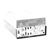
MANUAL CHANGES MODEL 5304A (05304-90006) Page
3
CHANGE
5
(Serial Prefix
No.
2024A)
Page 9D-6-3
A2
(05304-60003), Replaceable Parts:
>Change
A2
(05304-60003) Series Number
to
2024A.
Page 9D-6-4
A2
(05304-60003)* Replaceable Parts:
>Change
A2S1, S2 and S3
from 3101-2383
to
3101-1313;SWITCH-SLIDE DPDT
0.5A
125V
28480; 3101-1313.
CHANGE
6
Pages 90-6-3
and
9D-6-4, Table 9D-6-1.
A2
(05304-60003) Replaceable Parts:
>Change
A2
SERIES number
to 2148.
>Change
A2S1, S2 and S3 to
3101-2383; SWITCH-SLIDE DP3T MINTR
,5A
125VAC
PC
Page 9D-8-5# Figure 90-8-1.
A2
Attenuator Board Assembly Schematic Diagram:
>Change
A2
SERIES number
to 2148, at top of
schematic.
//CHANGE
7
Page 9D-6-3, Table 9D-6-1.
A1
(05304-60001) Replaceable Parts:
>Change
A1U21 to
05300-80013;
IC
GATE
ECL
0R-N0R, DUAL 2-INP
Page 9D-8-5, Figure 9D-8-1.
A1
Time Interval Board Assembly Schematic Diagram:
>Change
A1U21
part number
to
05300-80013
in
TABLE
OF
ACTIVE COMPONENTS.


 To Next Page
 Loading...