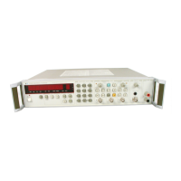
Model 5334A
General Information
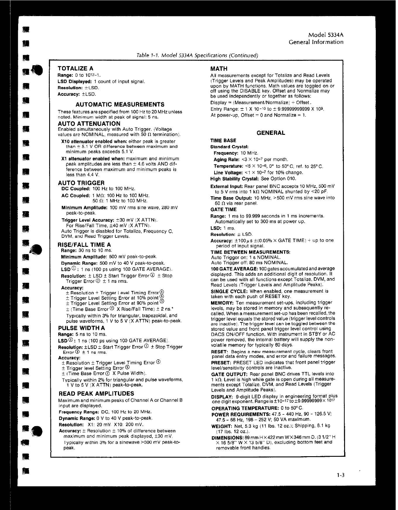
Table ‘i-7. Model 5334A Specifications (Continued)
TOTALIZE A
Range: 0 to 10’2-1.
LSD Displayed: 1 count of input signal.
Resoluuon: *LSD.
Accuracy: ZkLBO.
AUTOMATIC MEASUREMENTS
These featuresarespecified from 100 Hzto 20 MHz unless
noted. Minimum width at peak of signal: 5 ns.
AUTO ATTENUATION
Enabled simultaneously with Auto Trigger. (Voltage
values are NOMINAL, measured with 50 0 termination).
X10 attenuator enabled when: either peak is greater
than i- 5.1 V OR difference between maximum and
minimum peaks exceeds 5.1 V.
X1 ettenuetor enabled when: maximum and minimum
peak amplitudes are less than ?I 4.6 volts AND dif-
ference between maximum and minimum peaks is
less than 4.4 V.
AUTO TRIGGER
DC Coupled: 100 Hz to 100 MHz.
AC CouPled: 1 MO: 100 Hz to 100 MHz
50 ft 1 MHz to 100 MHz.
Minimum Amplitude: 100 mV rms sine wave, 260 mV
peak-to-peak.
Trigger Level Accuracy: ?;30 mV IX ATTN).
For Rise/Fall Time. ?40 mV IX ATTNI.
Auto Trigger is d&led for Totalize, Frequency C
DVM, and Read Trigger Levels.
RISE/FALL TIME A
Flange: 30 ns to 10 ml*.
Mtnimum Amplitude: 500 mV peak-to-peak.
Dynamic Range: 500 mV to 40 V peak-to-peak.
LSD@: 1 ns ilO0 ps using 100 GATE AVERAGE).
Resolution: i LSD i- Start Trigger Error@ i Stop
Trigger Error@ i 1 ns rms.
Accuracy:
+ Resolution ? Trigger Level Timing Error@
t Trigger Level Setting Error at 10% point@
+ Trigger Level Setting Error at 90% point @
i- (Time Base Error@-X Rise/Fall Time1 i- 2 ns.’
Typically within 3% for triangular, trapezoidal. and
pulse waveforms, 1 V to 5 V IX ATTNI peak-to-peak.
PULSE WIDTH A
Range: 5 ns to 10 ms.
LSD@: 1 ns (100 ps using 100 GATE AVERAGE).
Resotuffon: *LSD ? Start Trigger Error @ f Stop Trigger
Error @ + 1 “s rms.
Accuracy:
t Resolution + Trigger Level Timing Error @
2 Trigger level Setting Error@
i (Time Base Error@ X Pulse Widthl.
Typically within 2% for triangular and pulse WaVefOrmS.
1 V to 6 ” (X ATTN) peak-to-peak.
READ PEAK AMPLITUDES
Maximum and minimum peaks of Channel A or Channel B
input are displayed.
Frequency Range: DC, 100 Hz to 20 MHz.
Dynamic Range: 0 V to 40 V peak-to-peak.
Resotutlon: x1: 20 mv. x10: 200 mv.
Accuracy: + Resolution i- 10% of difference between
maximum and minimum peak displayed. t30 mV.
Typically within 3% for a sinewave ,500 mV peak-to-
peak.
MATH
All measurements except for Totalize and Read Levels
(Trigger Levels and Peak Amplitudes) may be operated
upon by MATH functions. Math values are toggled on or
off using the DISABLE key. Offset and Normalize may
be used independently or together as follows:
Display = (Measurement/Normalize) + Offset,
Entry Range: 2 1 x IO-10 to 2 9.99999999999 x
109.
At power-up, Offset = 0 and Normalize = I.
GENERAL
TIME BASE
Standard Cry&t:
Frequency: 10 MHz.
Aging Rate: ~3 X 10-T per month.
Temperature: 6 X 10⁻⁶, 0” to 5O*C, ref. to 250~.
Line “ottage: <I X 10-T for 10% change.
High Stability Crystal: See Option 010.
External Input: Rear panel BNC accepts 10 MHz. 500 mV
to 5 V rms into 1 kIl NOMfNAL shunted by ~20 pF.
Time Base Output: 10 MHz, ,500 mV rms sine wave into
50 Cl via rear panel.
GATE TIME
Range: 1 ms to 99.999 seconds in 1 ms increments.
Automatically set to 300 ms at power up.
LSD: 1 ms.
Resolution: i- LSD.
Accuracy: i1OOps ?(0.05% X GATE TlMEi + up to one
period of input signal.
TIME BETWEEN MEASUREMENTS:
Auto Trigger on: 1 s NOMINAL.
Auto Trigger off: 80 ms NOMINAL.
IOOGATEAVERAGE: IOOgatesaccumulatedandaverage
displayed. This adds an additional digit of resolution. It
can be used with a,, functions except Totalize, DVM, and
Read Levels (Trigger Levels and Amplitude Peaksl.
StNGLE CYCLE: When enabled, one measurement is
taken with each push of RESET key.
MEMORY: Ten measurement set-ups, including trigger
levels, may be stored in memwy and subsequently re-
called. When a measurementset-up has been recalled,the
trigger level equals the stored value (trigger level COntlOlS
are inactive). The trigger level can be toggled between the
stored value and front panel trigger level control using
DACS ON/OFF function. With instrument in STBY or AC
power removed, the internal battery will supply the non-
volatile memory for typically 60 days.
RESET: Begins a new measurement cycle, clears front
pane, data entry modes. and error and failure messages.
PRESET: PRESET LED indicates that front panel trigger
level/sensitivity controls are inactive.
GATE OUTPUT: Rear panel BNC drives TTL levels into
1 kn. Level is high while gate is open during all measure-
ments except Totalize, DVM, and Read Levels (Trigger
Levels and Amplitude Peaks).
DISPLAY: g-digit LED display in engineering format plus
onedigitexponent. Rangeisk10-17to?-9.99999999X 10”
OPERATING TEMPERATURE: 0 to 5O’C.
POWER REQUIREMENTS: 47.5 - 440 Hz, 90 - 126.6 V;
47.5 - 66 Hz, 196 - 252 V: 50 VA maximum.
WEIGHT: Net, 5.3 kg (11 Ibs. 12 oz.); Shipping, 6.1 kg
117 Ibs. 12 oz.,.
DI’MENStONS:6~mmHx422mmWX346mmD.(31/2”H
x 16 518” W x 13 516” D). excluding bottom feet and
removable front handles.
 Loading...