Model 5334A
General Information
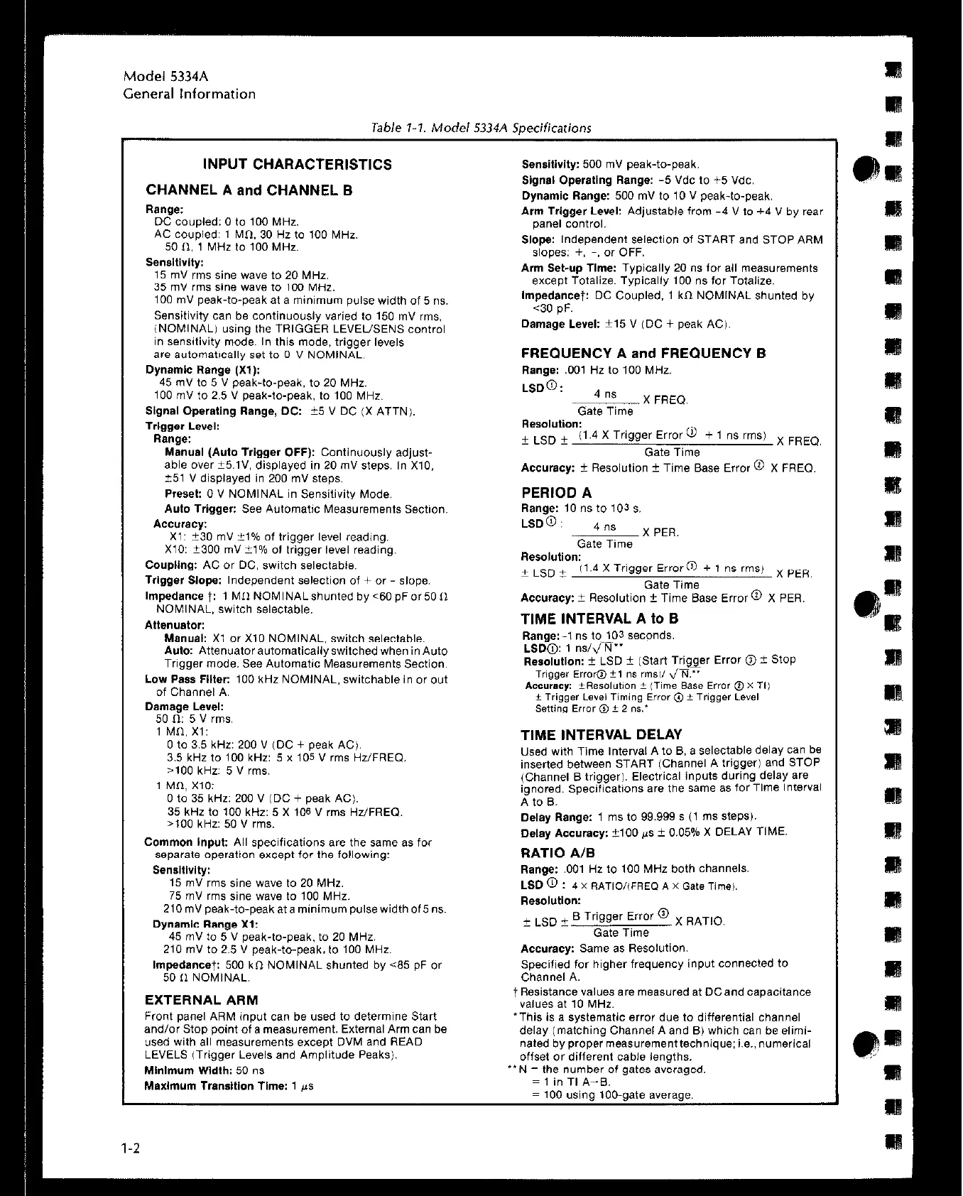
Table 7-7. Model 5334A Soecifications
INPUT CHARACTERISTICS
CHANNEL A and CHANNEL B
Range:
DC coupled: 0 to 100 MHz.
AC coupied: 1 MI>. 30 Hz to 100 MHz
50 II, 1 MHZ to 100 MHZ.
Sensitivity:
15 mV rms sine wave to 20 MHz.
35 mV rms sine wave to 100 MHz.
100 mV peak-to-peak et a minimum pulse width of 5 ns.
Sensitivity can be continuously varied to 150 mV rms.
iNOMINAL using the TRIGGER LEVEUSENS control
1” sensitivity mode. In this mode, trigger levels
are automatically set to 0 V NDMfNAL.
Dynamic Range (Xl):
45 mV to 5 V peak-to-peak, to 20 MHz.
100 mV to 2.5 V peak-to-peak. to 100 MHz.
Signal Operating Range, DC: i-5 V DC (X ATTN).
Trkmer Level:
“”
Range:
Manual (Auto Trigger OFF): Continuously adjust-
able over t5.1”. displayed in 20 mV steps. In X10,
?51 V displayed in 200 mV steps.
Preset: 0 V NOMINAL in Sensitivity Mode.
Auto Trigger: See Automatic Measurements Section.
Accuracy:
X1: i-30 mV “1% of trigger level reading.
X10: k300 mV 21% of trigger level reading
Coupling: AC or DC, switch selectable.
Trtgger Slope: Independent selection of + or - slope.
Impedance +: 1 MI1 NOMINAL Shunted by 60 pF or 50 II
NOMINAL, switch selectable.
Attenuator:
Manual: Xl or X10 NOMINAL, switch selectable.
Auto: Attenuator automatically switched when in Auto
Trigger mode. See Automatic Measurements Section.
Low Pass Filter: 100 kHz NOMINAL, switchable in or out
of Channel A.
Damage Level:
50 n: 5 v rms.
1 MCI, x1:
0 to 3.5 kHz: 200 ” ,DC
+ peak AC).
3.5 kHz to 100 kHz: 5 x
105” rms Hz/FRED.
>lOO kHz: 5” rms.
1 MCI. X10:
0 to 35 kHz: 200” IDC + peak AC,.
35 ktiz to 100 kHz: 5 X 10⁶ V rms Hz/FREQ.
,100 kHz: 50 V rms.
Common Input: All specifications are the same as for
separate operation except for the following:
Sensitlvlty:
15 mV rms sine wave to 20 MHz.
75 mV rms sine wave to 100 MHz.
ZlOmVpeak-to-peakataminimumpulsewidthof5ns.
oynemic Range x1:
45 mV to 5 V peak-to-peak. to 20 MHz.
210 mV to 2.5 V peak-to-peak. to 100 MHz.
tmpedancet: 500 kn NOMINAL shunted by ~85 pF or
50 II NOMINAL.
EXTERNAL ARM
Front panel ARM input can be used to determine Start
and/or Stop point of a measurement. External Arm can be
used with all measurements except DVM and READ
LEVELS (Trigger Levels and Amplitude Peaks).
Mlnlmum Wldth: 50 ns
Maxlmum TransItion Time: 1 ~5
Sensitivity: 500 mV peak-to-peak.
Signal Operating Range: -5 Vdc to +5 Vdc.
Dynamic Range: 500 mV to 10 V peak-to-peak.
Arm Trigger Level: Adjustable from -4 V to +4 V by rear
pane, control.
Slope: Independent selection of START and STOP ARM
slopes: +, -, or OFF.
Arm Set-up Time: Typically 20 ns for all measurements
except Totalize. Typically 100 ns for Totalize.
tmpedancet: DC Coupled. 1 kn NOMINAL shunted by
60 pF.
Damage Level: _+15 V IDC + peak AC).
FREQUENCY A and FREQUENCY B
Range: ,001 Hz lo 100 MHz.
LSD@:
4 ns
X FREQ.
Gate Time
Resolution:
+ LSD ~ (1.4 X Trigger Error @ + 1 ns rms)
Gate Time
X FREO.
Accuracy: + Resolution i Time Base Error @ X FREO.
PERIOD A
Range: 10 ns to 103 s
LSD-a :
4 ns
X PER.
Gate Time
Resolution:
+ LSD + 11.4 X Trigger Error@ + 1 ns rms) x PER
Gate Time
Accuracy: ? Resolution + Time Base Error @ X PER.
TIME INTERVAL A to B
Range:-, ns to 103 seconds.
LSD@: 1 r&m”
TIME INTERVAL DELAY
Used with Time Interval A to B, a selectable delay can be
inserted between START IChannel A trigger1 and STOP
(Channel B trigger). Electrical inputs during delay are
ignored. Specifications are the same as for Time Interval
A to B.
Delay Range: 1 ms to 99.999 s (1 ms steps).
Delay Accuracy: +I00 fis k 0.05% X DELAY TIME.
RATIO A/B
Range: ,001 Hz to 100 MHz both channels.
LSD 0 : 4 x RATIWFREQ A x fate ~imei.
Resolution:
+ LSD i B Trigger Error @
X RATIO.
Gate Time
Accuracy: Same as Resolution.
Specified for higher frequency input connected to
Channel A.
+ Resistance values are measured at DCand capacitance
w,lJe* et 10 MHZ.
‘This is a systematic error due to differential channel
d&w imatchinc! Channel A and Bi which can be elimi-
nateb byprope;measurementtechnique: i.e..numerical
offset or different cable lengths.
“N = the number of gates averaged.
= 1 in Tf A-B.
= 100 using too-gate average.
 Loading...