•
•
••
HP
5384A
and
HP
5385A
Operation
and
Programming
0
•
•
•
0
0
(hp
5384A
FREQUENCY COUNTER
Hf
WU:
r1 • PACKARD
I [
INPUTS
t.,.'IAfJUAl
fAll>
UVfl
A
,..
·i#?+·it]·i·M#;!;i•i·li.l:f·Ji
.J
POWER
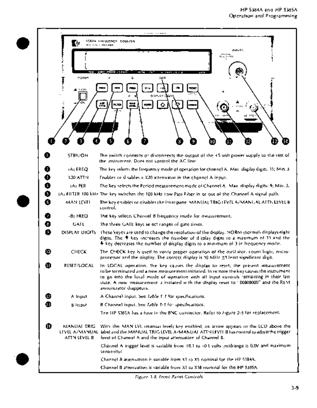
STBY/ON
(A)
FREQ
X20
ATTN
A
B
A
The switch connects
or
disconnects the
output
of
the
+5
volt
power''supply
to
the rest
of
the
instrument. Does
not
control
the
AC
line
.
The key selects the frequency mode
of
operation for channel
A.
Max. display digits:
11;
Min.
3
Enables
or
disables a
X20
attenuator
in
the
channel A
input.
(A)
PER
The key selects
the
Period measurement
mode
of
Channel A. Max. display digits: 9;
Min.
3.
(A)
Fl
LTER
100
kHz The key switches the
100
kHz
Low
Pass
Filter
in
or
out
of
the
Channel A signal path .
MAN
LEVEL
The key enables
or
disables
the
front
panel
MANUAL
TRIG
LEVEL
A/MANUAL
ATTN
LEVEL
B
control.
f)
(B)
FREQ
The key selects Channel B frequency
mode
for
measurement.
0
GATE
The
three
GATE
keys
select ranges
of
gate times.
0 DISPLAY DIGITS These keyes are used
to
change the resolution
of
the
display.
NORM
(normal) displays
eight
digits. The + key increases the
number
of
display digits
to
a
maximum
of
11
and
the
+ key decreases
the
number
of
display digits
to
a
minimum
of
3
in
frequency
mode.
G)
CHECK The CHECK key
is
used
to
verify
proper
operation
of
the
oscillator,
count
logic,
micro-
processor and
the
display. The correct display
is
10
MHz
±1
least significant digit.
0
RESET
/LOCAL
In LOCAL
operation,
the
key
causes
the
display
to
reset,
the
present measurement
to
be
terminated
and a
new
measurement initiated. In
remote
the key causes
the
instrument
to
go
into
the
local
mode
of
operation
with
all
input
controls remaining in
their
last
state. A
new
measurement
is
initiated
with
the
display reset
to
"00000000" and
the
REM
annunciator
diappears.
0 A
Input
A Channel
input.
See
Table
1-1
for specifications.
G)
B
Input
B Channel
input.
See
Table 1-1
for
specifications.
The
HP
53B5A
has
a fuse in
the
BNC
connector.
Refer
to
Figure 2-5
for
replacement.
MANUAL
TRIG
With
the
MAN
LVL
(manual level) key enabled,
an
arrow appears in the LCD above
the
LEVEL
A/MANUAL
label and
the
MANUAL
TRIG
LEVEL
A/MANUAL
ATTN
LEVEL
B
has
control
to
adjust the trigger
ATTN
LEVEL
B level
of
Channel A and the
input
attenuation
of
Channel
B.
Channel A trigger level
is
variable
from
+0.1
to
-0.1 volts (midrange
is
O.OV
and maximum
sensitivity) .
Channel B attenuation
is
variable
from
X1
to
XS
nominal for the
HP
5384A.
Channel B attenuation
is
variable
from
X1
to
X18
nominal
for
the
HP
5385A.
Figure 3-8. Front Panel
Controls
3-9