II I
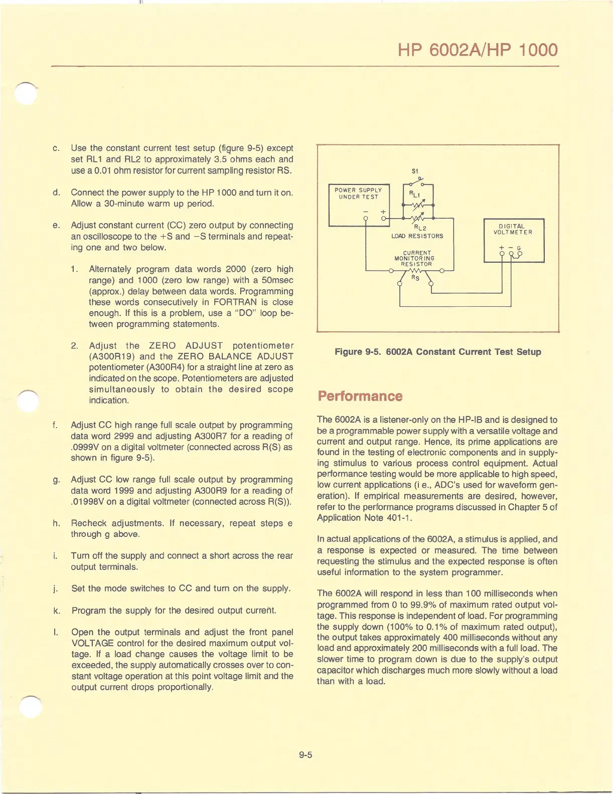
c. Use the constant current test setup (fiQure 9-5) except
set RL 1 and RL2 to approximately 3.5 ohms each and
use a
0.01
ohm resistor for current sampling resistor RS.
d. Connect the power
supply to the HP 1000 and turn
it
on.
Allow a 30-minute warm up period.
e.
Adjust constant current (CC) zero output by connecting
an
oscilloscope to the
+S
and
-S
terminals and repeat-
ing one and two
below.
f.
g.
h.
i.
j.
k.
I.
1.
Alternately program data words 2000 (zero high
range) and 1000 (zero low range) with a 50msec
(approx.) delay between data words. Programming
these words consecutively in
FORTRAN is close
enough. If this
is
a problem, use a
"DO"
loop be-
tween programming statements.
2.
Adjust
the
ZERO
ADJUST
potentiometer
(A300R19)
and
the
ZERO
BALANCE
ADJUST
potentiometer (A300R4) for a straight line at zero as
indicated on the scope. Potentiometers are adjusted
simultaneously
to
obtain
the
desired
scope
indication.
Adjust
CC
high range full scale outPl:lt by programming
data word 2999 and adjusting
A300R7 for a reading of
.0999V on a digital voltmeter (connected across R(S) as
shown
in
figure 9-5).
Adjust
CC
low range full scale output by programming
data word 1999 and adjusting A300R9 for a reading
of
.01998V on a digital voltmeter (connected across R(S)).
Recheck adjustments.
If necessary, repeat steps e
through g above.
Turn off the
supply and connect a short across the rear
output terminals.
Set the mode switches to CC and turn on the supply.
Program the supply for the desired output current.
Open the output terminals and adjust the front panel
VOLTAGE control
for the desired maximum output vol-
tage.
If
a load change causes the voltage limit to be
exceeded, the supply automatically crosses over to con-
stant
voltage operation at this
pOint
voltage limit and the
output current drops proportionally.
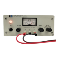
9-5
HP 6002A/HP 1000
51
"
0--
POWER SUPPLY
RL1
UNDER
TE ST
yI':-
-
+
~
vt_
~L2
DIGITAL
VOLTMETER
LOAD
RES I STORS
+ - G
CURRENT
~
MONITOR
ING
RES I STOR ...().
{RS
~
Figure 9-5. 6002A Constant Current Test Setup
Performance
The 6002A is a listener-only on the HP-IB and is designed to
be a programmable power supply with a versatile voltage and
current and output range. Hence, its prime applications are
found
in
the testing of electronic components and
in
supply-
ing stimulus to various process control equipment. Actual
performance testing would be more
applicable to high speed,
low current applications
(i
e., ADC's used for waveform gen-
eration).
If empirical measurements are desired, however,
refer to the performance programs discussed in Chapter 5 of
Application Note
401-1.
In
actual applications of the 6002A, a stimulus is applied, and
a response is expected
or
measured. The time between
requesting the stimulus and the expected response is often
useful information to the system programmer.
The
6002A will respond
in
less than 100 milliseconds when
programmed from
0 to 99.9%
of
maximum rated output
~Ol
tage. This response is independent of load. For programming
the supply down (100% to
0.1
% of maximum rated output),
the output takes approximately
400 milliseconds without any
load and approximately
200 milliseconds with a full load. The
slower time to program down is due to the supply's output
capaCitor which discharges much more
slowly without a load
than with a load.