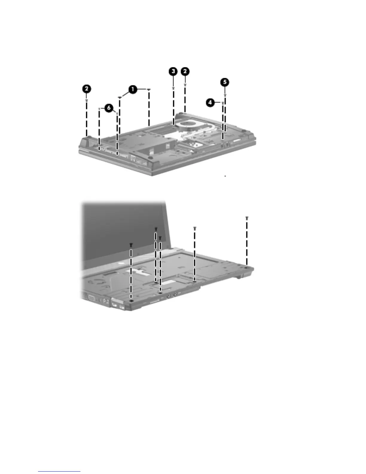
3.
Remove the two Phillips PM2.0×2.0 screws (1) located in the battery bay, the five Torx M2.5×6.0
screws (2), (3), (4), and (5), and the two Phillips PM2.0×3.0 screws (6) located in the recess
near the optical drive.
4. Turn the computer over so it is right-side up and remove five Torx M2.5×6.0 screws.
Component replacement procedures
81