•
•
•
SECTION
III
OPERATING
INSTRUCTIONS
3-1
OPERATING
CONTROLS
AND
INDICATORS
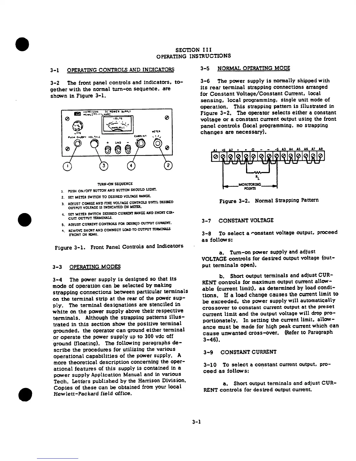
3-2
The front panel
controls
and
indicators,
to-
gether
with
the
normal
turn-on
sequence,
are
shCM'n
in Figure
3-1.
0
ll(f(I
TURN-ON
SEQUENCE
I.
PUSH
ON/OFF
BUTTON
ANO
BUTTON
SHOULO
LIGHT.
2.
SET
METER
SWITCH
TO
C&SIREO
VOLTAGt
llAN'GE.
3.
ADJUST
COARSE
AND
nNE
VOLTAGE
CONTROLS
UNTIL
lXSllED
OUTPUT
VOLTAGE
IS
INOICATl:D
ON
METER
•
~.
SET
METER
SWITCH
DESIRED
CURRENT
ltANGt
AND
SHORT
CIR•
CUIT
OUTPUT
TERMINALS.
s.
ADJUST
CURRENT
CONTROLS
f'OR
cc;nu;o
OUTPUT
ci.nuu:m.
~.
R.CMOV!:
SHORT
AND
CONNECT
~TO
OUTPUT
TERMINALS
ll'RONT
OR
REAR!.
Figure
3-1.
Front
Panel Controls and
Indicators
3-3
OPERAnNG
MODES
3-4
The power
supply
is
desiqned so
that
its
mode
of
operation
can
be
selected
by
making
strapping
conne~tions
between
particular
terminals
on
the
terminal
strip
at
the
rear
of
the
power
sup-
ply.
The terminal
designations
are
stenciled
in
white
on
the
power
supply
above
their
respective
terminals.
Although
the
strapping
patterns
Ulus-
trated
in
this
section
show the
positive
terminal
grounded,
the
operator
can
ground
either
terminal
or
operate
the
power
supply
up
to
300
vdc off
ground
(floating). The following paragraphs
de-
scribe
the
procedures
for utilizing the various
operational
capabilities
of
the power supply. A
more
theoretical
description
concerning the
oper-
ational
features
of
this
supply
is
contained
in a
power
supply
Application Manual and in
various
Tech.
Letters
published
by
the
Harrison Division.
Copies
of
these
can
be
obtained from your
local
Hewlett-Packard
field
office.
3-1
3-5
NORMAL
OPERATING
MODE
3-6
The power supply
is
normally shipped with
its
rear
terminal
strapping connections arranged
for
Constant
Voltage/Constant
Current,
local
sensing,
local
programming, single unit
mode
of
operation.
This
strapping pattern
is
illustrated
in
Figure
3-2.
The operator
selects
either
a
constant
voltage
or
a
constant
current
output using the front
panel
controls
Oocal
programming, no strapping
changes
are
necessary}.
Figure
3-2.
Normal Strapping
Pattern
3-7
CONSTANT
VOLTAGE
3-8
To
select
a
ronstant
voltage output,
proceed
as
follows:
a.
Turn-on power supply and
adjust
VOLTAGE
controls
for
desired
output voltage {out-
put
terminals
open).
b.
Short
output
terminals and
adjust
CUR-
RENT
controls
for maximum output current
allow-
able
(current
limit),
as
determined by load
condi-
tions.
If
a
load
change
causes
the
current limit
to
be
exceeded,
the
power
supply
will
automatically
crossover
to
constant
current
output
at
the
preset
current
limit
and
the
output
voltage
will
drop
pro-
portionately,
In
setting
the
current limit,
allow-
ance
must
be
made for high peak current which
can
cause
unwanted
cross-over.
(Refer to Paragraph
3-46).
3-9
CONSTANT
CURRENT
3-10
To
select
a
constant
current output.
pro-
ceed
as
follows:
·
a.
Short
output terminals and
adjust
CUR-
RENT
controls
for
desired
output current.
 Loading...