•
•
•
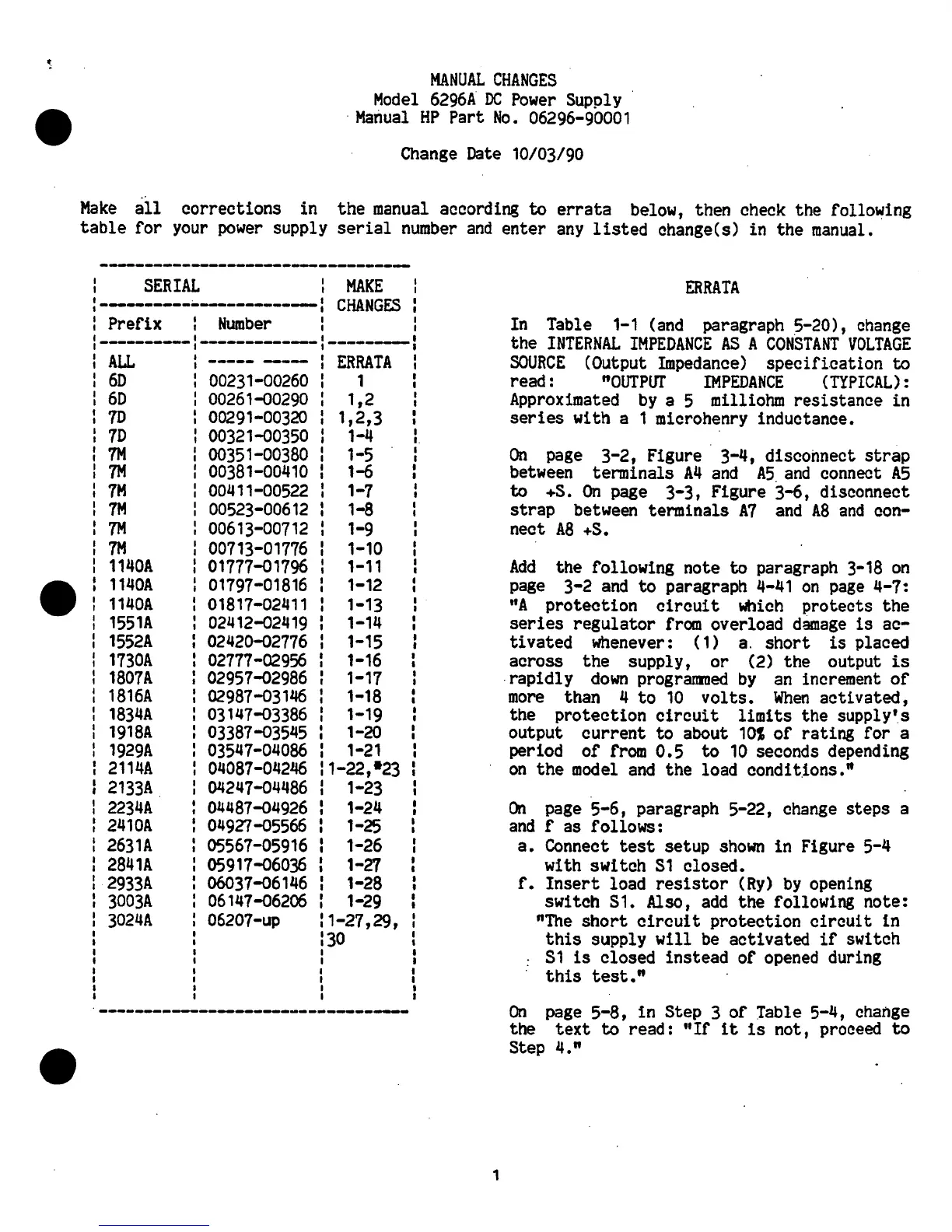
MANUAL
CHANGES
Model
6296A
DC
Power
Supply
·
·
Manual
HP
Part
No.
06296-90001
Change
Date
10/03/90
Make
all
corrections in the
manual
according
to
errata
below, then
check
the following
table
for
your
power
supply
serial
number
and
enter
any
listed
change(s) in the
manual.
SERIAL
MAKE
:----------•-------------:
CHANGES
: Prefix
Number
I
I
·----------
-------------·---------
ALL
-----
---
ERRATA
60
00231-00260
1
60
00261-00290
1,2
70
00291-00320
1,2,3
70
00321-00350
1-4
7M
00351-00380
1-5
7M
00381-00410
1-6
7H
00411-00522
1-7
7M
00523-00612
1-8
7M
00613-00712
1-9
7H
00713-01776
1-10
1140A
01777-01796
1-11
1140A
01797-01816
1-12
1140A
01817-02411
1-13
1551A
02412-02419
1-14
1552A
02420-02776
1-15
1730A
02777-02956
1-16
1807A
02957-02986
1-17
1816A
02987-03146
1-18
1834A
03147-03386
I
1-19
1918A
03387-03545
1-20
1929A
03547-04086
1-21
2114A
04087-04246
1-22,•23
2133A
04247-04486
1-23
2234A
I
04487-04926
1-24
2410A
04927-05566
1-25
2631A
05567-05916
1-26
2841A
05917-06036
1-27
2933A
06037-06146
1-28
3003A
06147-06206
1-29
3024A
06207-up
1-27,29,
30
----------------------------------
I
I
I
I
I
I
I
1
ERRATA
In
Table
1-1
(and
paragraph
5-20),
change
the
INTERNAL
IMPEDANCE
AS
A
CONSTANT
VOLTAGE
SOURCE
(Output
Impedance)
specification
to
read:
"OUTPl1l'
IMPEDANCE
{TYPICAL):
Approximated
by
a 5 milliohm resistance in
series
with a 1 microhenry inductance.
On
page
3-2, Figure 3-4, disconnect
strap
between
terminals
A4
and
A5.
and
connect
A5
to
+S.
On
page
3-3, Figure 3-6, disconnect
strap
between
terminals
A7
and
AS
and
con-
nect
A8
+S.
Add
the following note
to
paragraph
3-18
on
page
3-2
and
to
paragraph
4-41
on
page
4-7:
"A
protection
circuit
which
protects the
series
regulator
from
overload
damage
is
ac-
tivated whenever: (1)
a.
short
is
placed
across the supply, or (2) the output
is
rapidly
down
progranmed
by
an
increment
of
more
than 4
to
10
volts.
When
activated,
the protection
circuit
limits
the supply's
output current to about
101
of
rating for a
period of
from
0.5
to
10
seconds depending
on
the
model
and
the load conditions."
On
page
5-6, paragraph 5-22,
change
steps a
and
f as follows:
a.
Connect
test
setup
shown
in Figure 5-4
with switch
51
closed.
f.
Insert
load
resistor
(Ry)
by
opening
switch
S1.
Also,
add
the following note:
"The
short
circuit
protection
circuit
in
this
supply
will
be
activated
if
switch
: S 1
is
closed instead of
opened
during
·
this
test."
On
page
5-8,
in
Step 3 of Table 5-4,
change
the
text
to
read :
"If
it
1 s not, proceed
to
Step 4."
 Loading...