DRAFT 27
Operation and Service Manual
Performance Tests Procedures
7 Disconnect the power meter from the test set and connect a short to INPUT PORT A
(measuring S
11
at INPUT PORT A). Calibrate the network analyzer for a 0 dB return
loss reference on the display. Use the center horizontal graticule line. Note the TEST
CHANNEL GAIN at the reference:
8 Disconnect the short from INPUT PORT A. Terminate the amplifier OUTPUT with 50
Ω. Connect INPUT PORT A to the amplifier INPUT.
9 Set the TEST CHANNEL GAIN 10 dB above the reference in step 7. The center hori-
zontal graticule line now represents a return loss of 10 dB. The measured return loss
should be as shown below:
10 Repeat steps 8 and 9, measuring return loss at the amplifier OUTPUT. Terminate the
amplifier INPUT with 50Ω. The measured return loss should be as shown below:
11 Set the sweep oscillator to sweep each of the ranges shown below, repeating steps 7
through 10 for each range.
Reference TEST CHAN. GAIN, 110 to 220 MHz: ___________dB
INPUT VSWR, 110 to 220 MHz
HP 8447D, >9.6 dB:__________ HP 8447F Preamp, >9.6 dB:_____________
HP 8447E, >8.8 dB:__________ HP 8447F Power amp, >8.8 dB:__________
HP 8447D Output VSWR, 110 to 220 MHz: 8.8 dB _____________
HP 8447E/F Output VSWR, 110 to 220 MHz: 7.7 dB _____________
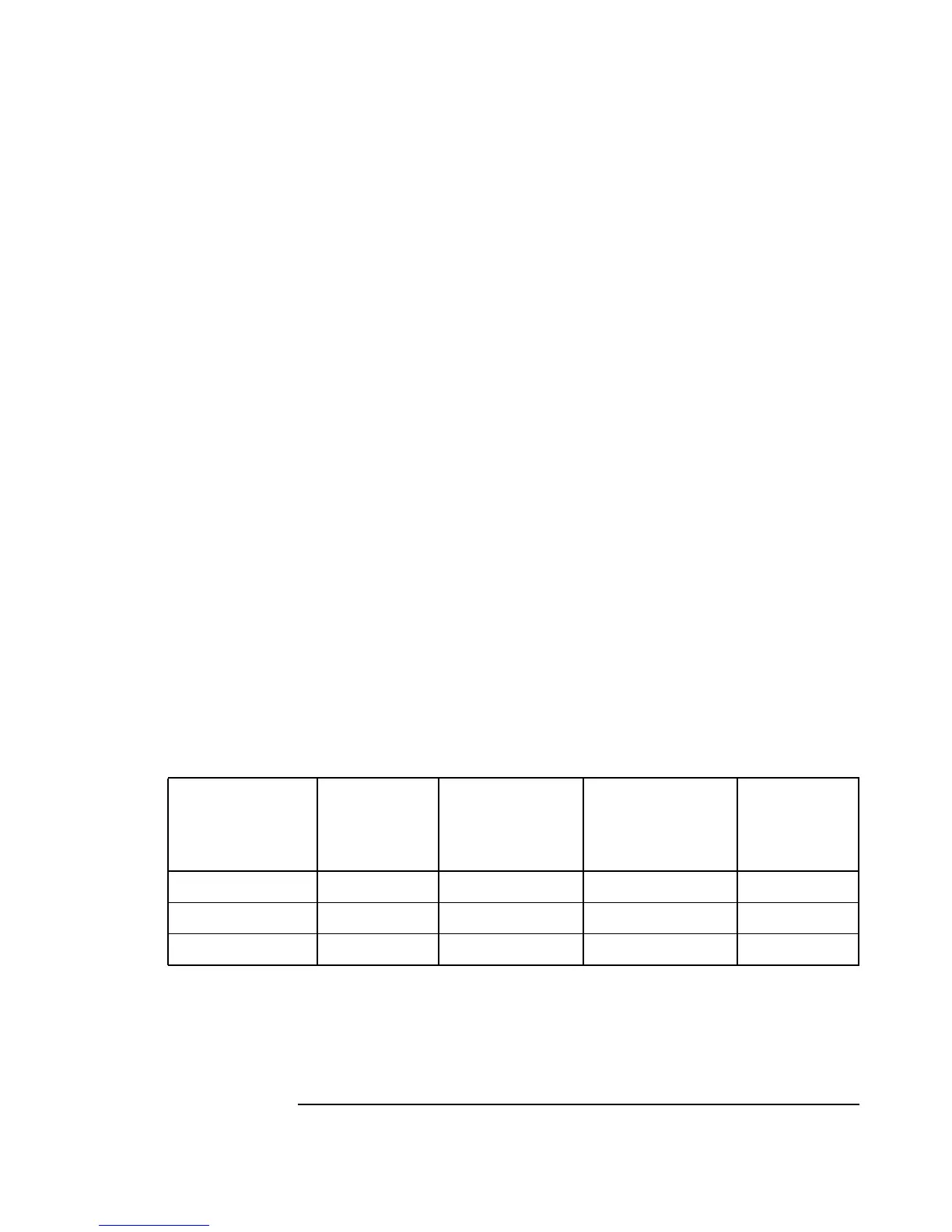
Sweep Range
Reference,
Test Chan.
Gain
HP 8447D Input,
HP 8447F Preamp
Input
HP 8447D Output,
HP 8447E Input,
HP 8447F Power
Amp Input
HP 8447E/F
Output
220 to 440 MHz _________dB __________dB ___________dB __________dB
440 to 880 MHz _________dB __________dB ___________dB __________dB
880 to 1300 MHz _________dB __________dB ___________dB __________dB