DRAFT 33
Operation and Service Manual
Adjustment Procedure
Adjustment Procedure
Power Supply Voltage Check and Adjustment
Description:
To insure that the amplifier gives proper gain, the power supply is adjusted to 20V
±0.1V.
Equipment:
Digital voltmeter . . . . . . . . . . . . . . . . . . . . . . . . . . . . . . . . . . . HP 3440A/3444A
RMS voltmeter. . . . . . . . . . . . . . . . . . . . . . . . . . . . . . . . . . . . . . . . . . . HP 3400A
Cable assembly (w/test clips). . . . . . . . . . . . . . . . . . . . . . . . . . . . . . . HP 10501A
Adapter. . . . . . . . . . . . . . . . . . . . . . . . . . . . . . . . . . . . . . . . . . . . . . . . HP 10111A
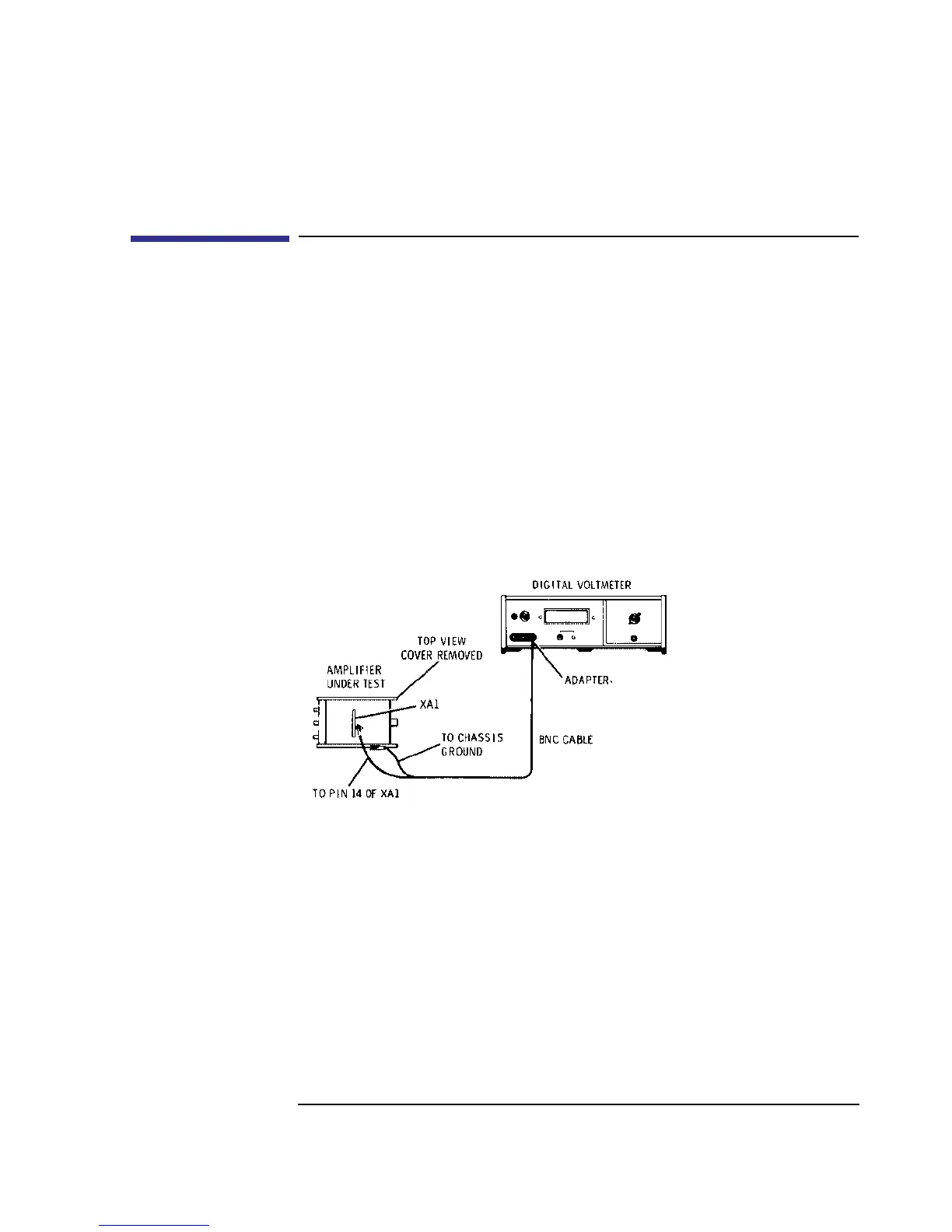
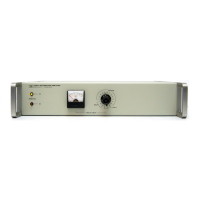
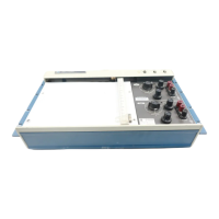
Figure 10 Power Supply Voltage Adjustment Test Setup
Procedure:
1 Connect the test setup in Figure 10. Set the digital voltmeter to measure +20V dc.
2 Adjust A1R9 VOLT ADJ for a digital voltmeter reading of +20V ±0.1V dc.
3 Remove the digital voltmeter from the amplifier and connect the RMS voltmeter to
XA1 pin 14. The ripple voltage should be as shown below.
DVM: +19.9V dc _________________+20.1V dc