"
,1.
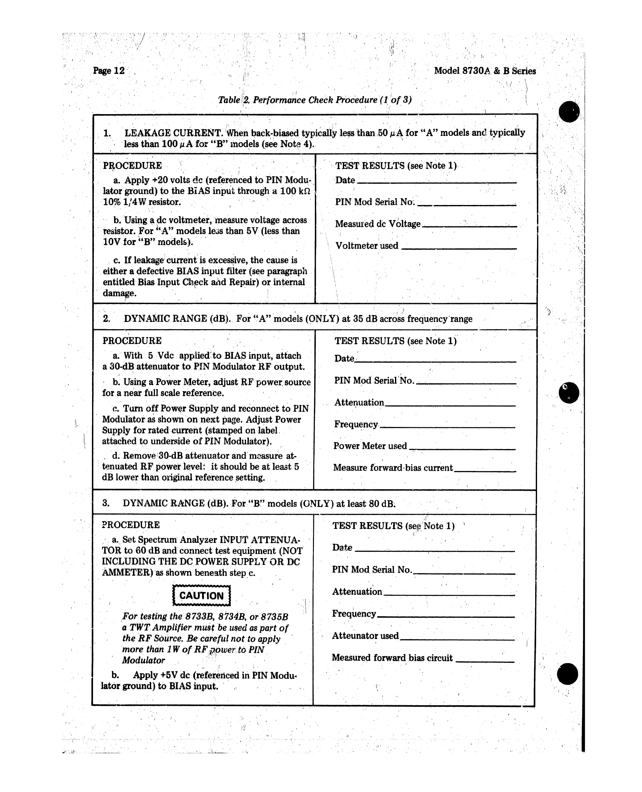
'LEAKAGE CURRENT.
<When
back-biased
typica11~
less
than,50J.t4
for
"A"
models
and
typically
'lesstlian
lQO
~A
for'
"B"lnod~ls
(see
Not?
4). . '
.'"
( . . '," ;
."
,'i
,
r-'~
, I
;; / ,i ,
Tablei2. Performance CheckProcedure
'(1,'of3)
,,"
'\,),
.
1'1'"
_<I
I
!,
.•
, ,.
,'I
'
, ,I '
, '
\
I
/ I
:1
s :
Mddel
8730A
& B
Series
!
, II .
,ii,
I,
,
I
,i
'
"
,
,)
~
" .
,I,
'
,.'
I
"j
ii,
"1
, "
'-",,'
,','"
'? '
,
',.,/
.'
,'.
'/
, I
Page 12",
v.'.
, )
,
,l
, ' I ,/ •
DYN'AMIC
R~NGE
(dB)., .For ','A" models
(9NLY)at
35 dB across frequencyrange
, '
,.
,"
'.
,
i:,
I
,
~'1
.'
\ ,
,
,)
.
'.
lao.. .
'I
, ,
Voltmeter.
used
_
PIN Mod Serial
No'~'_.,_.....;....
......
"
Measured de Voltage
L;
__
TEST
RESULTS (see Note 1),
, '
'Date
_.
-,-
__
, ,
2.
.PROCEDURE
\'
\," " I
a.
Apply +20
voltsde
(re(eren~ed
to
PIN Modu-.
lator
ground)
to
the
BlA,S inptit through a 10Q
kn
...
'10%
1/4W
resistor.
I"
, ,
. b. Using a de
voltmeter,
'measure voltage across
.
'resistor.
For
"A"
models less
than
5V (less
than
"
'I,
, , '
lOV
for
"B"
models).
, c.
If
leakage!current'is excessive,
the
cause is
.,.
either
a defective BIAS
input
filter (see paragraph .
entitled
Bias
Input
Check and Repair)
or
internal
·dam~e.
' ,
",
I
) ,
PROCEDURE ,
',,
I
a.' With, 5 "Vdc
appliedto
BIA,S
input,
attach
a80-dB
attenuator
to
PIN Modulator RF
output.
,I \ ,
I b. Using a Power Meter, adjust
RF
power, source
fot
a near full scale reference.
c.
Turn
off
Power
Supply
and
reconnect
to
PIN
Modulator
as
shown
'on
next
page. Adjust Power
Supply
for
rated current (stamped on label, .
attached
to
underside
of
PIN
Modulator).
, d. Remove.
"30-dBattenuator
and'measure at-
•tenuated
RF
power level:
it
should be
at
least 5
dB lower
than
original reference setting,
TEST
RESULTS (see Note
1)
Date
.
....;..,
, _
PIN
Mod Serial(No.
..;...;._~----_·
,
.,
Attenuation
~------
Frequ~ncy,_-----------
Power
Meter used -:-- _
Measure forwardI bias current
-----
a,
'.
3. DYNAMIC RANGE (dB).
,For"B"
models (ONLY) 'at least' 80
dB~
,\ -.'.
I "
Date
~-~-----
PIN Mod Serial No. _
PROCEDURE
.'.
a.
Set
Spectrum' Analyzer
INrUT
ATTENUA- '
TOR
to
60
dB and
connect
test
equipment (N01'i
INCLUDING THE DC POWER
SUPPLY
OR DC
AMMETER)
'~
shown beneath step,c.
t-----------:---------.....;...----r------~----./~
---------:-----1
TEST
RESULTS
(self~,INotel)
)
~'
.
"
,
.,
"
",-
"
J
,
, .,
I .
Frequency
--
_
,
Attenuation
---
_
Measured
forward
bias'circuit _
,
Atteunator
used _
"
.~.,',\
For
testing the 8733B, 8734B, or 8735B
'a
TWT,Amplifier must beused as
part
of
the
RF
Source.
Be earefutnotto apply
, 'more than 1W
of
R~i,)pwer:to
PIN.
Modulator,
•
.:
. '
, i
,I
\
II'
I \ •
b. Apply +5V
de
(referenced in PIN
Modu
..
Jatar ground)
to
BIAS
input.
' ,
,\
"
-,
1-)
'r,
\'
, '
.'--~_._.,-
 Loading...